
user manual

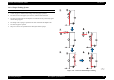
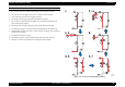
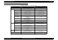
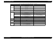
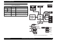
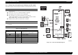


Table Of Contents
- EPSON EPL-6200/EPL-6200L
- Contents
- Product Description
- 1.1 Outline
- 1.2 Basic Specifications
- 1.2.1 Process Specifications
- 1.2.2 Printer Basic Specifications
- 1.2.3 Paper Specification
- 1.2.4 Reliability, Durability, Serviceability
- 1.2.5 Operating Conditions (Including Consumables)
- 1.2.6 Storage and Transport of the Printer Main Unit and Optional Products (Consumables Packaged)
- 1.2.7 Electrical Features
- 1.2.8 Compliance with Standards and Regulations
- 1.2.9 Consumable Components
- 1.3 External Appearance and Parts Name
- 1.4 Controller Specification
- 1.5 Control Panel (EPL-6200)
- 1.6 Control Panel (EPL-6200L)
- 1.7 RAM Expansion
- 1.8 System Requirements (Only for EPL-6200L)
- 1.9 Paper Feed Specifications (Only for EPL-6200L)
- 1.10 Notes on Operation
- 1.11 Status Sheet
- 1.12 Ambient Conditions
- 1.13 Differences in Specifications between Intended Markets
- 1.14 Notes on Installation of Optional Units
- Operating Principles
- 2.1 Overview
- 2.2 Description of Mechanisms
- 2.3 Operating Principles of Electric Circuitry
- Troubleshooting
- 3.1 Overview
- 3.2 Troubleshooting When There is Error Display
- 3.2.1 Fuser warming up problem
- 3.2.2 Fan problem
- 3.2.3 Polygon Motor Error
- 3.2.4 Laser problem
- 3.2.5 High voltage circuit problem
- 3.2.6 Fuser high temperature problem
- 3.2.7 CPU Error
- 3.2.8 Engine Communication Error
- 3.2.9 Fuser low temperature problem
- 3.2.10 Standard RAM Error
- 3.2.11 RAM Error (Slot 0)
- 3.2.12 ROM Checksum Error (Font)
- 3.2.13 ROM Checksum Error (Program)
- 3.2.14 Option ROM Error
- 3.2.15 EEPROM Error
- 3.2.16 Engine Initialization Error
- 3.2.17 Other Hardware Error
- 3.2.18 Software Error
- 3.3 Troubleshooting for Paper Jam
- 3.4 Troubleshooting for Abnormal Operations
- 3.5 Troubleshooting for Electrical Parts
- 3.6 Troubleshooting for Print Quality Problems
- Disassembly and Assembly
- Adjustment
- Maintenance
- Appendix

EPSON EPL-6200/EPL-6200L Revision A
Operating Principles Operating Principles of Electric Circuitry 98
2.3.1.2 Main Control Circuit Board (C533Main) for EPL-6200L
EPL-6200L employs a newly developed controller for ESC/PageS Printing System.
PRINCIPAL FEATURES
All the functions, including those of the CPU, are incorporated in one ASIC
(called “SLC2”).
As the CPU core, C33 core made by EPSON is employed.
The algorithm of the extension circuit is BitRepeat3.
This controller is a fruit of the full pursuit of cost reduction:
2 MB of RAM (SDRAM is used), no optional RAM, no RITech and PGI
(EnhancedMicroGray), and resolution fixed to 600 dpi
Parallel interface (Nibble, ECP) and USB 1.1 interface
CONSTITUTION OF MAIN CONTROL CIRCUIT BOARD
Main Board Assy:
C534 MAIN
MAJOR ELEMENTS
Figure 2-35. C534 Controller Block Diagram
Table 2-12. Major Elements
Name Location Remarks
CPU/Clock -
EPSON
32bit-RISC CPU S1C33000, 24MHz
ASIC SLC2 IC100 E01A32AA
TTL IC105 SN74AHCT244PWR
ROM IC103
Reset IC: IC107 M51953BFP-600C
Regulator IC106 PQ033EZ01ZP
EEPROM IC104 S93C46ADFJ
SDRAM IC101 MSM56V16160F-10TS-K