ABLE Systems Limited DENTON DRIVE, NORTHWICH, CHESHIRE, CW9 7TU, ENGLAND Tel: +44 (0)1606 48621 Fax:+44 (0)1606 44903 e-mail: contact@able-systems.com Website: www.able-systems.com USER GUIDE to the Ap1310-DC Thermal Printer Revision: Filename: Date: “1.2” “AP1310DCusg12.
1 1 2 2.1 2.2 2.3 2.4 3 3.1 3.2 4 4.1 4.2 5 6 6.1 6.2 6.3 6.4 7 7.1 8 8.1 8.2 8.3 8.4 8.5 8.6 8.7 9 9.1 9.2 9.3 9.4 9.5 TABLE OF CONTENTS Table Of Contents ........................................................................................................................ 2 Introduction................................................................................................................................... 3 Notes on Printer Firmware Revisions (Including Flash) ................................
2 INTRODUCTION This document is a User Guide, written for the person connecting and using the Able Systems Ap1310-DC thermal printer. Please read this Guide carefully before making any connection. A separate Programmer Guide provides details of the control codes, and describes the internal operation of these products. 2.1 NOTES ON PRINTER FIRMWARE REVISIONS (INCLUDING FLASH) Able Systems reserves the right to modify and improve the firmware in its printer products at any time.
2.
3 MODES OF OPERATION The Ap1310-DC has two operating modes, when not actually printing: "Idle Mode": ready to accept data, but no data are in the buffer awaiting printing, and the printer motor is not running; "Spool Mode": active, but storing data for later printing. Modes are indicated by different colour combinations on the front-panel LED (see section 6).
4 PAPER Pressing the paper feed button when the printer is idle, or in spool mode, advances paper at typically 50 mm per second. However, the feed button has additional functions: "Double-clicking" the button: (i.e. pressing and releasing twice in quick succession just like a PC mouse) in idle mode, prints a demo/test message including the firmware version, encoded calibration data, and the full character set; in spool mode, or having been out of paper, prints any stored data and enters idle mode.
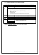
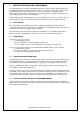
5 LED INDICATIONS The LED indicator at the front of the Ap1310-DC has a number of colour combinations, which repeat in up to a 4-phase pattern to provide status information (see table below). In summary, if the LED is constant green it indicates that the printer is operating normally. Flashing on and off indicates that Spool mode is active and no printing can take place. Red warns of a low power supply voltage or other problem. No light indicates that the unit is off.
6 PRINTER OPERATION AND PROGRAMMING The Ap1310-DC utilises a Fujitsu FTP-628MCL103 printer mechanism, with a fixed (parallel) print head with 384 horizontally-arranged thermal elements. The paper is advanced by a stepper motor, and printing takes place in a single dot row for each step of the paper. Each printed dot is approximately 1/8 mm square. The printing speed and dot density are controlled according to the power supply voltage and the head temperature.
7 7.1 INTERFACE DETAILS RS-232 SERIAL INTERFACE The Ap1310-DC printer has an industry standard RS-232 interface. The default parameters are 9600 baud, 8 data bits, 1 stop bit and no parity. Other baud rates can be programmed by control codes, or by using a setup utility available from the factory. Serial data is expected in standard RS-232C format with -12V meaning 'mark' or '1' and +12V a logical '0', with reference to the common ground.
8 8.1 CONNECTIONS AND EMC PRECAUTIONS CABLING DETAILS The Ap1310-DC has a single moulded cable, see below for connection details. 8.
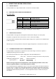
8.5 DATA CABLE You can attach a suitable data cable terminated with a female D9 connector. As a guide the pinout for a standard 9 way PC comm port (male) is given below. D-9 Pin 3 2 6&8 5 8.6 Name TxD RxD CTS & DSR SGND Function (refers to PC) Serial Data Output Serial Data Input Busy Input Signal Common 0V EMC STATEMENT The Ap1310-DC is fully EMC (Electro-Magnetic Compatibility) compliant and is CE marked accordingly.
9 GETTING STARTED You may find that you can connect up the printer to your Personal Computer (PC), and everything works perfectly first time. However, there are many variables, and the following guide may help if you find you need some assistance. These are only suggestions, and may not work with all PC’s. 9.1 CONNECTING TO A PC – A CHECKLIST First, you need to GET THE PRINTER GOING Make sure that the power supply is switched on and connected.
It is important to recognise that other Windows printer drivers, even for ESCPOS compatible printers, may not work with the Ap1310-DC, as they format everything as dot graphics patterns, in a way which is unique to each kind of printer. The Windows “Generic Text Only” printer driver should, however, work in a limited manner. 9.3 YOUR APPLICATION PROGRAM Once communications between your computer and the printer have been established, you can try driving the printer from your application program.