
User's Manual


-I/O CH CK (I)
I/O channel check provides the system board with parity (error)
information about memory or devices on the I/O channel. When this
signal is active, it indicates an uncorrectable system error.
I/O CH RDY (I)
“I/O channel ready” is pulled low (not ready) by a memory or I/O device
to lengthen I/O or memory cycles. Any slow device using this line
should drive it low immediately upon detecting its vaild address and a
Read or Write command. Machine cycles are extended by an integral
number of clock cycle (167 nanoseconds). This signal should be held
low for no more than 2.5 microseconds.
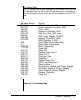
IRQ3-IRQ7, IRQ9-IRQ12 and IRQ 14 through 15 (I)
Interrupt Requests 3 through 7, 9 through 12, and 14 though 15 are
used to signal the microprocessor that an I/O device needs attention.
The interrupt requests are prioritized, with IRQ9 through IRQ12 and
IRQ14 through IRQ15 having the highest priority (IRQ9 is the highest)
and IRQ3 through IRQ7 having the lowest priority (lRQ7 is the lowest).
An interrupt request is generated when an IRQ line is raised from low
to high. The line must be held high until the microprocessor acknow-
ledges the interrupt request (Interrupt Service routine). Interrupt 13 is
used on the system board and is not available on the I/O channel.
Interrupt 8 is used for the real-time clock.
-lOR (I/O)
“-I/O Read” instructs an I/O device to drive its data onto the data bus.
It may be driven by the system microprocessor or DMA controller, or
by a microprocessor or DMA controller resident on the I/O channel.
This signal is active low.
-IOW (I/O)
“-I/O Write” instructs an I/O device to read the data on the data bus. It
may be driven by any microprocessor or DMA controller in the system.
This signal is active low.
Chapter 6: Appendix
37