Bi-directional Parallel Interface Board B80818* Installation Manual lnstallationshandbuch Manuel d'installation Manual de lnstalacion Manuale di lnstallazione 4005242 COl-01
FCC Compliance Statement For United States Users This equipment has been tested and found to comply with the limits for a Class B digital device, pursuant to Part 15 of the FCC Rules. These limits are designed to provide reasonable protection against harmful interference in a residential installation. This equipment generates, uses and can radiate radio frequency energy and, if not installed and used in accordance with the instructions, may cause harmful interference to radio or television reception.
EPSON ® All rights reserved. No part of this publication may be reproduced, stored in a retrieval system, or transmitted in any form or by any means, electronic, mechanical, photocopying, recording, or otherwise, without the prior written permission of Seiko Epson Corporation. No patent liability is assumed with respect to the use of the information contained herein. Neither is any liability assumed for damages resulting from the use of the information contained herein.
Declaration of Conformity According to ISO/IEC Guide 22 and EN 45014 Manufacturer: Address: SEIKO EPSON CORPORATION 3-5, Owa 3-chrome, Suwa-shi, Nagano-ken 392 Japan Representative: Address: EPSON EUROPE B.V. Prof. J. H. Bavincklaan 5 1183 AT Amstelveen The Netherlands Introduction . . . . . . . . . . . . . . . Installation . . . . . . . . . . . . . . . Einfiihrung . . . . . . . . . . . . . . . Installation . . . . . . . . . . . . . . .
Installation . . . . . . . . . . . . . . . . . . . . . . . . . . . . . 4 Installation . . . . . . . . . . . . . . . . . . . . . . . . . . . . . 4 Installation . . . . . . . . . . . . . . . . . . . . . . . . . . . . . 4 Instalacih . . . . . . . . . . . . . . . . . . . . . . . . . . . . . . 4 Installazione . . . . . . . . . . . . . . . . . . . . . . . . . . . . .
The Bi-directional Parallel Interface Board is designed for use with IBM®-compatible personal computers. This board can be used only to connect your computer to an EPSON color image scanner. To connect the board to the scanner, use a shielded parallel interface cable that has a DB25 (D-sub 25 pin) male connector on one end and a Centronics®-type 36-pin connector on the other. To install the interface board in your computer, you will need a crosshead (+) screwdriver.
La carte d’interface parallele bidirectionnelle a et6 conpe pour une utilisation avec des ordinateurs persormels compatibles IBM(R). Cette carte doit uniquement servir ?I raccorder votre ordinateur & un digitaliseur d’images couleurs EPSON. Pour raccorder la carte au digitaliseur, utiliser un cable d’interface parallPle blind6 muni d’un connecteur mile DB25 (D-Sub B 25 broches) a une extrkmite et d’un connecteur de type Centronics(R) a 36 broches de l’autre.
La scheda d’interfaccia parallela bidirezionale e’ stata progettata per l’installazione su personal computer IBM compatibili. Questa scheda puo’ essere usata per collegare il computer a uno scanner Epson a colori. Per collegare la scheda allo scanner dovete usare un cave di interfaccia parallel0 schermato con un connettore DB2S (D-sub 25 pin) a un’estremita’ e un connettore tipo Centronics a 36 pin dall’altra. Per installare la scheda nel computer e’ necessario un cacciavite con la testa a croce.
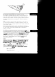
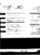
Unpack the bidirectional board, and hold it by its edges. 2. Caution: Do not touch the parts on the board or the board connector. Jumper Vergewissern Sie sich, daB der Computer ausgeschaltet und vom Netz getrennt Functio Jl Select LPTl ( J2 Factory use (do n J3 B only (do not Jumper Jl selects the parallel interface p cases, the computer is already equipped printer and uses the Ll’Tl setting. Nom board’s default setting, which is LPT2.
2. You may need to change the jumper setting on the interface board to match your computer’s settings. If so, simply lift off the jumper plug (J1) and reinstall in over the proper pins as shown. Jumper Function Factory setting J1 Select LPT1 or LPT2 LPT2 J2 Factory use (do not change) Open J3 B only (do not change) B Jumper J1 selects the parallel interface port address: LPT1 or LPT2.
est possible de changer le Gglage de cavalier sur la carte d’interface pour qu’il corresponde aux rbglages de l’ordinateur. 11 suffit d’enlever le cavalier 01) et de I’ins&er sur les broches appropri&s, comme indique. Cavalier Fonction Rbglage d’udne Jl SBlectionne LPTl ou LPT2 LPT2 J2 Position d’usine (Ne pas changer) Ouvert J3 B uniquement (Ne pas changer) B 3. Warning: Never remove the cover of the computer wh 4.
3. Make sure the computer is turned off and unplugged from the AC outlet. Warning: Never remove the cover of the computer while it is plugged into a power source. 4. Disconnect the keyboard, monitor, and all the cables and peripherals from the computer, and then move it to a place that will allow sufficient room for installation. Achtung: Beriihren Sie weder Teile auf der Karte mch auf den Steckverbindern. 4.
Face the back of the computer, and then remove the retaining screws. Keep the screws in a safe place while you work on the computer. 6. Remove the top cover. Entfemen Sie auf der Computerriickseite alle noch verbliebenen Schrauben. Bewahren Sie die Schrauben an einem sicheren Ort auf, wahrend Sie am Computer arbeiten. 6. Nehmen Sie die obere Abdeckung des 1 5. Se mettre face au dos de l’ordinateur puis retirer les vis de fixations.
6. Remove the top cover. 6. Nehmen Sie die obere Abdeckung des Computergeh&ws ab. 6. Retirer le capot superieur. 6. Retire la cubierta de1 rodenador. 6. Aprite il computer.
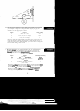
Choose a 16-bit option slot in which to install the board, and remove the screw and slot cover. 8. Insert the card gently into the slot in the not seem to fit, do not try to force it. Chl connectors and then reinsert the board. Wahlen Sie fir die Installation der Karte einen optionalen 16-Bit-Schnittstellenschacht und entfemen Sie die Schraube und die Abdeckung des Schnittstellenschachts. 8.
8. Insert the card gently into the slot in the correct direction. If the board does not seem to fit, do not try to force it. Check the alignment of the connectors and then reinsert the board. 8. Schieben Sie die Karte vorsichtig in den Schnittstellenschacht. Wenn die Karte nicht pa&, versuchen Sie es nicht mit Gewalt. ijberprtifen Sie die Ausrichtung der Steckverbinder und schieben Sie die Karte anschliel3end ein. 8. Introduire doucement la carte dans la fente, dans le sens correct.
Be sure that it is firmly seated in the slot. Secure the board with the screw you removed from the slot cover. 9. Vergewissem Sie sich, da13 sie fest im Schnittstellenschacht sitzt. Schrauben Sie die Karte mit der Schraube fur die Abdeckung des Schnittstellenschachts fest. 9. S’assurer qu’elle soit bien ancr6e dans la fente. Fixer la carte au moyen de las vis qui servait I maintenir la protection de la fente. Asegurese de que este correctamente asentada en la ranura.
screws. 10. Setzen Sie die obere Abdeckung des Computers wieder auf und schrauben Sie die mit den verbliebenen Schrauben fest. 10. Remonter le capot supkieur de l’ordinateur et l’attacher avec les vis de fixation. 10. Coloque de nuevo la cubierta de1 ordenador y ase@rela con sus tomillos. 10. Chiudete il computer e riawitate le viti di chiusura.
11. 11. 11. 11. Reconnect the keyboard, monitor, and peripherals to the computer. Make sure you use a properly shielded parallel interface cable to connect the bidirectional interface board to your scanner. Next, reconnect the computer and peripherals to power outlets. 12. SchlieBen Sie die Tastatur, den Monitor und die Peripheriegerate an den Computer an.
12. Turn on the computer and check to see that it operates correctly. Note: lf you have a diagnostic program for the computer, run it before starting up the entire system to ensure that the board was installed correctly. 12. Schalten Sie den Computer ein und iiberptifen Sie, ob er ordnungsgemlf?, arbeitet. Hinweis: Wenn Sk ein Priifprogrammjir den Computer haben, starten Sie es zuerst, urn sicherzustellen, daj3 die Carte korrekt installiert worden ist und starten Sie erst a&n das vollsthdige System. 12.
EPSON OVERSEA 13. Run your scanner software program as a final check. EPSON AMERICA, INC. 20770 Madrona Ave. P.O. Box 2842 Torrance, CA 90509-2842 Phone: (800) 922-8911 Fax: (310) 7825220 EPSON DEUTSCHLAND GmbH Ziilpicher StraBe 8, 40549 Diisseldorf Germany Phone: (0211) 58030 Telex: 8584786 EPSON AUSTRALIA PTY. LTD. 70 GIBBES STREET, CHATSWOOD 2087 C Phone: 2-9903-9000 Fax: 2-9903-9177 13. Lancer le programme du logiciel du digitaliseur pour une verification finale. EPSON HONG KONG LTD.
I EPSON OVERSEAS MARKETlNG LOCATlONS I EPSON AMERICA, INC. EPSON UK LTD. 20770 Madrona Ave. P.O. Box 2842 Torrance, CA 90509-2642 Phone: (600) 922-6911 Fax: (310) 762-5220 Campus 100. Maylands Avenue, Hemel Hempstead, Herts. HP2 7TJ, U.K. Phone: (+44) 01442 61144 Fax: (+44) 01442 227227 EPSON DEUTSCHLAND GmbH EPSON FRANCE S.A. Zijlpicher StraSe 6. 40549 Dgsseldort Germany Phone: (0211) 56030 Telex: 6564766 66 bis, rue Marjolin 92300, Levallois-Perret, France Phone: 33.1.40.67.37.
EPSON