
Service manual

EPSON Stylus Photo R200/R210 Revision A
DISASSEMBLY AND ASSEMBLY Disassembly 55
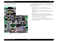
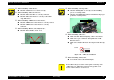
o When reinstalling "CSIC Board",
n Check if "CSIC Board" is secured correctly.
o When reinstalling "PW Sensor Board",
n Check if "PW Sensor FFC" is correctly connected.
n Check if "PW Sensor Board" is correctly secured with
"Cap, PW Sensor".
o When reinstalling "CR Encoder Sensor Board",
n Check if "CR Encoder Sensor Board" is correctly secured.
n Check if "CR Encoder Sensor Board" is correctly
connected.
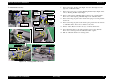
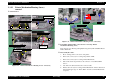
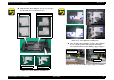
o When reinstalling "Holder, Scale, Right (Left)",
n Check if "Slider, Holder, Scale" is set.
Figure 2-26. "Slider, Holder, Scale" installation
Slider, Holder, Scale
o When reinstalling "Carriage Unit",
n Check if "Timing Belt" is correctly set to the installing
groove of "Carriage Unit".
n Check if "Grounding Plate, Head" is installed to the proper
position of "Carriage Unit".
Figure 2-27. Installation Position of "Grounding Plate, Head"
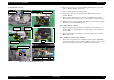
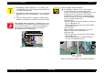
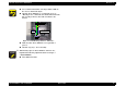
o When reinstalling "CR Scale",
n Make sure that "Extension Spring, 3.289" is not twisted.
n Make sure to pass "CR Scale" through the slit of "CR
Encoder Sensor".
n Make sure to install "CR Scale" the cut-part on the left edge
up.
Figure 2-28. "CR Scale" installation
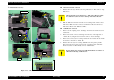
o When reinstalling "Guide, CR",
n Screw in the order as shown in the figure.
C A U T I O N
Do not adhere the grease at the contact point of ’Carriage’ and
"CR Lock Lever". Otherwise, fatal error may possible occur
because ’CR Lock Lever’ is not moved.
Grounding Plate, Head
Cut-Part