SERVICE MANUAL Scanner • Printer • Copier EPSON Stylus PHOTO RX600/610 , RX620/630 SEOT03006 Download Service Manual And Resetter Printer at http://printer1.blogspot.
Notice: All rights reserved. No part of this manual may be reproduced, stored in a retrieval system, or transmitted in any form or by any means, electronic, mechanical, photocopying, recording, or otherwise, without the prior written permission of SEIKO EPSON CORPORATION. The contents of this manual are subject to change without notice. All effort have been made to ensure the accuracy of the contents of this manual.
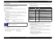
PRECAUTIONS Precautionary notations throughout the text are categorized relative to 1)Personal injury and 2) damage to equipment. DANGER Signals a precaution which, if ignored, could result in serious or fatal personal injury. Great caution should be exercised in performing procedures preceded by DANGER Headings. WARNING Signals a precaution which, if ignored, could result in damage to equipment.
About This Manual This manual describes basic functions, theory of electrical and mechanical operations, maintenance and repair procedures of the printer. The instructions and procedures included herein are intended for the experienced repair technicians, and attention should be given to the precautions on the preceding page. Manual Configuration This manual consists of six chapters and Appendix. CHAPTER 1.PRODUCT DESCRIPTIONS Provides a general overview and specifications of the product. CHAPTER 2.
Revision Status Revision Date of Issue A December 10, 2003 B February 2, 2004 Description First release CHAPTER 3 TROUBLESHOOTING • 3.2 Troubleshooting at Unit Level / Table 3-1 LCD Indication (p.21) is modified. CHAPTER 4 DISASSEMBLY AND ASSEMBLY • • • • • • 4.1.5 Stylus PHOTO RX600/610, RX620/630 Disassembly (p.40) is modified. 4.5 Disassembly and Assembly of Printer Unit (p.50) is modified. 4.5.3 Printhead (p.54) is added. 4.5.7 Front Frame Assembly (p.58) is added. 4.5.8 Front Paper Guide (p.
EPSON Stylus PHOTO RX600/610, RX620/630 Revision C CONTENTS Chapter 1 Product Description 3.1.1 Specified Tools ......................................................................................... 20 3.1.2 Preliminary Checks ................................................................................... 20 1.1 Overview .............................................................................................................. 9 1.1.1 Basic Functions ...........................................
EPSON Stylus PHOTO RX600/610, RX620/630 Revision C 4.4.1 Upper Housing Assembly Removal ......................................................... 4.4.2 CCD Module ............................................................................................. 4.4.3 Motor Assembly ...................................................................................... 4.4.4 HP Sensor Circuit Board .......................................................................... 48 49 49 49 4.
1 CHAPTER PRODUCT DESCRIPTION Download Service Manual And Resetter Printer at http://printer1.blogspot.
EPSON Stylus PHOTO RX600/610, RX620/630 Revision C Standalone Copier function 1.1 Overview The latest six color dye type printer engine allows to make photo quality copies on the Epson special coated paper. Other features are as follows: This section describes the specifications for the SPC (Scanner, Printer, Copier) machine “Stylus PHOTO RX600/610, RX620/630”. 1.1.
EPSON Stylus PHOTO RX600/610, RX620/630 Revision C Compatible to various memory cards. 1.2 Common Compact Flash / Microdrive The specifications described below are common to the scanner and printer. Smart Media / xD-Picture Card Memory Stick / MagicGate Memory Stick / Memory Stick PRO / Memory Stick Duo* / SD Memory Card / miniSD Card* /MultiMediaCard 1.2.1 Electrical Specifications Table 1-1. AC Input Note “*”: Adapter required 1.1.
EPSON Stylus PHOTO RX600/610, RX620/630 Revision C 1.2.2 Interface 1.2.4 Environmental Conditions USB 2.0 compatible. See Table 1-2. for details. Table 1-4. Operating Storage Transporting*3 10 ~ 35 °C*1 - 20°C ~ 40°C*2 -20°C ~ 60 °C*1 Humidity (no condensation) 20 ~ 80%, RH 20 ~ 85% 5 ~ 85%, RH Resistance to physical shock 10-3 Table 1-2. Item Temperature Descriptions Standard “Universal Serial Bus Specifications Revision 2.
EPSON Stylus PHOTO RX600/610, RX620/630 1.2.7 Weight and Overall Dimensions Weight: 10.0 kg (Excluding ink cartridge) Overall Dimensions (mm): 455.9 x 439.1 x 256.0 (Width x Depth x Height) NOTE: Neither the rubber feet nor the paper tray is included. Revision C 1.3 Ink Cartridge Type: Special ink cartridge Suggested effective period: Period described on the product package, or six months after opening.
2 CHAPTER OPERATING PRINCIPLES Download Service Manual And Resetter Printer at http://printer1.blogspot.
EPSON Stylus PHOTO RX600/610, RX620/630 Revision C 2.1 Overview PF Motor This Chapter describes the operating principles of the mechanism and electric circuits of EPSON Stylus PHOTO RX600/610, RX620/630. Stylus PHOTO RX600/610, RX620/630 mainly, basically consists of a printer and a scanner. The mechanism can be divided into the printer and the scanner. The electric circuit includes the Main Board circuit, Power Supply Board circuit, scanner carriage circuit and control panel circuit. 2.
EPSON Stylus PHOTO RX600/610, RX620/630 2.2.1.1 Carriage Motor Specification Table 2-1. CR Motor Specification Item Type Specifications Revision C 2.2.1.4 PW Detector Specification Stylus PHOTO RX600/610, RX620/630 has newly employed a PW (Paper Width) sensor that is described in detail below. Purpose of Detection DC Motor with brush Voltage + 42V (DC) ±5% (printable voltage to the driver) Resistance 22.65 Ω ± 10% Inductance 17.
EPSON Stylus PHOTO RX600/610, RX620/630 Revision C 2.2.2 Scanner Mechanism Controlling of each detection Table 2-3.
EPSON Stylus PHOTO RX600/610, RX620/630 Revision C 2.3 Electric Circuit The electric circuit boards of Stylus PHOTO RX600/610, RX620/630 are as follows: C543MAIN Board (main circuit board) C543PSB Board / C543PSE Board (power supply circuit board) CCD circuit board (Scanner circuit board) Panel circuit board Figure 2-4.
EPSON Stylus PHOTO RX600/610, RX620/630 Revision C 2.3.1 C543 Main Circuit Board Table 2-4. Main Element 2.3.1.1 Feature • • • • • • USB 2.
3 CHAPTER TROUBLESHOOTING Download Service Manual And Resetter Printer at http://printer1.blogspot.
EPSON Stylus PHOTO RX600/610, RX620/630 Revision C 3.1 Overview 3.1.2 Preliminary Checks Before starting troubleshooting, be sure to verify that the following conditions are all met: With this printer, almost all troubles can be coped with by using “EPSON Status Monitor 3” installed on the host personal computer. Once an error occurs, the “EPSON Status Monitor 3” will appear as a pop-up window on the screen of the host PC. It will show details of how to cope with the trouble.
EPSON Stylus PHOTO RX600/610, RX620/630 Revision C 3.2 Troubleshooting at Unit Level Table 3-1. LCD Indication LCD Indication By following this troubleshooting procedure, when some trouble has occurred, you can easily identify the unit which is the cause of the trouble, from its observation. Table 3-1 and Table 3-2 list the observations of various troubles. Once the type of the trouble has been identified, refer to the flowchart for that trouble. EMC Printer error occurred.
EPSON Stylus PHOTO RX600/610, RX620/630 Revision C Table 3-2. Observations and Troubleshooting Flowcharts Observation Details Refer to Power is on but not operating • LED does not turn on at all. • Printer mechanism does not operate at all. • Scanner mechanism does not operate at all. Figure 3-2 Error is detected • LCD/LED panel shows error status. Figure 3-3 Trouble related to print • Printing is not done. • Print is abnormal (Dot missing, etc.). • Print quality is bad.
EPSON Stylus PHOTO RX600/610, RX620/630 Revision C 3.2.2 Error is detected 3.2.3 Trouble related to Print Start Start Execute test printing Check error contents by LCD (See Table 3-1). No Printing was successfully done? Yes Turn power off, unlock CR and move CR with hand. Printer error? Yes All the Yes cables are connected properly to main board? Yes No No Yes Replace Ink cartridge with a new one by operation panel.
EPSON Stylus PHOTO RX600/610, RX620/630 Revision C 3.2.4 Paper feeding is not normally carried out 3.2.5 Operation Panel faulty Start Paper is correctly set in ASF? Start No Operation Panel is connected properly with cable? No Set paper correctly. Yes Yes Paper loading roller and PF roller are correctly rotating? Connect correctly Operation panel again. No Yes No Problem is solved? PF motor is driving? Yes No Remove foreign matters, if any, from paper route.
EPSON Stylus PHOTO RX600/610, RX620/630 Revision C 3.3 Troubleshooting for Printer Table 3-3. Printer Errors (continued) Observation This section describes repair / service of the Printer Mechanism. Listed below are various problems which may occur, observations of such problems, check point and remedies. For the pertinent observation, check the functions of the parts in question according to Check Point. Table 3-3.
EPSON Stylus PHOTO RX600/610, RX620/630 Revision C Troubleshooting without error display on LCD. For Items and pages, refer the following: • • • • • • • • Faulty pump mechanism (p26) Ink is not absorbed at all or ink absorption is poor. (p26) Faulty carriage operation (p27) Printing is not carried out correctly. (p27) Faulty print (p28) Faulty paper loading (p30) Faulty paper ejection (p30) Printer stops during initialization (p31) Faulty pump mechanism Table 3-4.
EPSON Stylus PHOTO RX600/610, RX620/630 Revision C Faulty carriage operation Table 3-6. Diagnostics when carriage action is abnormal Condition When power is turned on, carriage operation is abnormal. Abnormal carriage operation during printing Cause Check Point Remedy There is an obstacle in CR shift area. Check with the naked eye whether there is an obstacle. Remove the obstacle. CR lock is not released. Check that change lever is in the front of printer.
EPSON Stylus PHOTO RX600/610, RX620/630 Revision C Faulty print Table 3-8. Diagnostics when printing is abnormal Condition Faulty printing occurs at specific dots. Sometimes dots are missing. Cause Check Point Remedy Head surface is dirty. (Dot missing occurs) Repeat cleaning and test printing alternately several times. Clean with a swab fixed to a stick. Faulty head FFC Check whether head FFC is damaged. Replace the head FFC with a new one.
EPSON Stylus PHOTO RX600/610, RX620/630 Revision C Table 3-8. Diagnostics when printing is abnormal (continued) Condition White line appears in output data. Troubleshooting Cause Check Point Remedy Dirt is adhering to CR guide shaft. Check whether dirt is adhering to the surface of CR guide shaft. Clean the surface of CR guide shaft with a dry and soft cloth. Faulty CR guide shaft. Check that CR guide shaft is steadily installed in the designated position.
EPSON Stylus PHOTO RX600/610, RX620/630 Revision C Faulty paper loading Table 3-9. Diagnostics when feeder is abnormal Condition Paper is not loaded. Check Point Remedy Paper loading roller worn Cause Check whether paper loading roller rotates when paper feeding is not operating. Check whether paper loading roller is not slipping during paper feeding. Check that Micro Pearl or oily substance is not adhering to the paper loading roller Clean the paper loading roller with the cleaning sheet.
EPSON Stylus PHOTO RX600/610, RX620/630 Revision C Printer stops during initialization Table 3-11. Diagnostics when printer stops during format Condition Printer error is indicated. Cause Check Point Faulty PE sensor Check PE sensor signal level. (Refer to Table 3-22 “Sensor Check” on page -35) Faulty CR HP sensor Check CR HP sensor signal level. (Refer to Table 3-22 “Sensor Check” on page -35) Remedy Replace the PE sensor Head FFC is not connected properly.
EPSON Stylus PHOTO RX600/610, RX620/630 Revision C Observation of Trouble and Reference for Remedy 3.4 Troubleshooting for Scanner This section describes repair / service for the Scanner mechanism. In troubleshooting, first the trouble is identified at the unit level based on the observation. According to the observation as described in Table 3-13, perform the necessary checking by referring to the appropriate table. Scanner Errors at User Level Table 3-12.
EPSON Stylus PHOTO RX600/610, RX620/630 Revision C Carriage unit does not operate Fluorescent lamp does not turn on Table 3-15. Carriage unit does not operate Cause Check Point Connector CN13 and CN14 on main board is disconnected. 1. Connector CN13 and CN14 on main board is disconnected? Faulty carriage moving mechanism 1. Grease is applied properly? Faulty CR motor Defective main board Yes/No - Remedy Connect the connector. Yes No 2.
EPSON Stylus PHOTO RX600/610, RX620/630 Revision C Failure diagnosis concerned with Memory Card Slot 3.5 I/F Concerned Troubleshooting This section describes the failure diagnosis on USB Interface, Memory Card Slot. USB Interface error Table 3-20. Failure diagnosis concerned with Memory Card Cause Check Point 1. On Windows, open “My Host PC does not support Windows 98 computer” → “Property” → “Device manager”. essentially.
EPSON Stylus PHOTO RX600/610, RX620/630 Revision C 3.6 Troubleshooting for Motors and Sensors Motor Resistance and Check Point Table 3-21. Motor Resistance and Check Point Section Printer Scanner Motor Name Location Check Point CR motor CN11 (Main board) Pin 1 & 3 PF motor CN12 (Main board) Pin 1 & 3, Pin 2 & 4 CR motor CN6 (HP board) Pin 1 & 3, Pin 2 & 4 Sensor Check Table 3-22. Sensor Check Section Sensor Name PE sensor Printer Scanner Location Off: CN10 / Pin 1 & 2 less than 0.
4 CHAPTER DISASSEMBLY AND ASSEMBLY Download Service Manual And Resetter Printer at http://printer1.blogspot.
EPSON Stylus PHOTO RX600/610, RX620/630 Revision C 4.1 Overview 4.1.1 Precautions See the precautions given under the handling “WARNING” and “CAUTION” in the following column before disassembling and assembling the product. This section describes procedures for disassembling the main components of the product. Unless otherwise specified, disassembly units or components can be reassembled by reversing the disassembly procedure.
EPSON Stylus PHOTO RX600/610, RX620/630 Revision C 4.1.3 Screws C A U T IO N Use only recommended tools for disassembling, assembling or Table 4-2. Screws adjusting the printer. Observe the specified torque when tightening screws. Apply lubricants and adhesives as specified. (See Chapter 6 for details.) Make the specified adjustments when you disassemble the printer. ( See Chapter 5 for details.) At assembly, make sure that the ink tube has been installed in the correct position.
EPSON Stylus PHOTO RX600/610, RX620/630 Revision C 4.1.4 Service Dispatch Standard Table 4-3. Check List (continued) Classification When this machine is completely repaired and returned to the user, confirm finally according to Check list in Table 4-3. Lubrication Part Designated lubrication items Table 4-3.
EPSON Stylus PHOTO RX600/610, RX620/630 Revision C 4.1.5 Stylus PHOTO RX600/610, RX620/630 Disassembly The flowchart below shows step-by-step disassembly procedure. When disassembling each component, refer to the page number shown in the figure. 4.2 Main Unit Removal (p.41) Disassembly and Assembly of Main Unit START 4.6 Disassembly and Assembly of Other Parts (p.60) Panel Unit Removal (p.41) Disassembly and Assembly of Panel Unit (p45) Scanner Unit Removal (p.
EPSON Stylus PHOTO RX600/610, RX620/630 Revision C 4.2 Main Unit Removal 4.2.1 Panel Unit Removal Operation Panel 1. Remove a USB cable from the Stylus PHOTO RX600/610, RX620/630 unit. 2. Remove the operation panel from the panel unit. 3. Remove two screws securing the panel unit. 4. Remove the panel unit from the printer. 5. Remove three screws that secure front housing. 6. Remove front housing from the printer. 7.
EPSON Stylus PHOTO RX600/610, RX620/630 Revision C 4.2.2 Scanner Unit Removal 1. Panel Unit Removal. (p41) 2. Remove one screw that secures the FFC cover. 3. Remove the FFC cover from the middle housing. 4. Remove a TPU cable and a Grounding cable from the printer unit. 5. Remove all main board connectors. 6. Remove ferrite core from the middle housing. 7. Remove two hinge screws that secure the middle housing. 8. Remove the scanner unit upward easily. C.B.P.
EPSON Stylus PHOTO RX600/610, RX620/630 Revision C 4.2.3 Middle Housing Removal C.B.P Tite 3x10,F/ZN Tightening torque:0.6 ± 0.1 N ⋅m 1. Scanner Unit Removal. (p42) 2. Remove all connectors from the main board. 3. Remove one screw that secures a tube cover, and remove it from the printer unit. 4. Remove four screws that secure the lower housing to the middle housing. 5. Remove the middle housing upwards. C H E C K P O IN T Middle Housing C.B.P Tite 3X8,F/ZN Tightening torque :0.6 ± 0.
EPSON Stylus PHOTO RX600/610, RX620/630 Revision C Pay attention when handling the connector while installing the middle housing. After installing the Middle Housing, remove the Tube Cover 1. 2. once and make certain that the tube is inserted into the Porous Pad properly. Remove the one screw securing the Tube Cover and remove the Tube Cover. Check that the tube is inserted into the Porous Pad properly. Tube Tube Cover Porous Pad C.B.P Tite 3X8,F/ZN Tightening torque:0.6 ± 0.
EPSON Stylus PHOTO RX600/610, RX620/630 Revision C 4.3 Disassembly and Assembly of Panel Unit 4.3.1 Panel Circuit Board Removal 1. Panel Unit Removal. (p41) 2. Remove one screw that secures the grounding plate. 3. Remove the grounding plate from the panel shield plate. 4. Remove six screws that secure the shield plate. 5. Remove the panel shield plate from the front middle cover. 6. Disconnect a harness from the panel circuit board. 7. Remove six hooks that secure the panel circuit board. 8.
EPSON Stylus PHOTO RX600/610, RX620/630 Revision C 4.3.2 LCD ASSY Removal 1. C.B.P Tite 3x10,F/ZN Tightening torque:0.6 ± 0.1 N ⋅m Remove the one screw securing the right bush. 2. Remove the right bush from the front middle cover. 3. Remove the one screw securing the LCD ASSY. 4. Remove the LCD ASSY from the front middle cover. 5. Remove the left bush. 6. Release the hook fixing the clutch spring. 7. Remove the clutch spring from the left bush. Front Middle Cover Left Bush C.B.
EPSON Stylus PHOTO RX600/610, RX620/630 Revision C 4.4 Disassembly and Assembly of Scanner Unit C A U T IO N START Perform disassembly and assembly for the scanner unit in an environment free from dust. You are advised to work in a clean room or on a clean bench, if possible. Ensure that there are no stains or scratches on the document table. Do not touch interior glass panel surface when installing the scanner housing. Handle glass panel surface with care by attaching protective sheet or paper.
EPSON Stylus PHOTO RX600/610, RX620/630 Revision C 4.4.1 Upper Housing Assembly Removal TPU Assembly 1. Scanner Unit Removal. (p42) 2. Remove the TPU assembly. 3. Remove four hinge screws. 4. Remove a hinge from the scanner unit. 5. Unlock the carriage. 6. Remove eight screws on bottom of the scanner unit. 7. Unhook two locations that secure the upper housing assembly to the lower housing. 8. Remove the upper housing assembly while positioning the document table up. C.B.
EPSON Stylus PHOTO RX600/610, RX620/630 Revision C 4.4.2 CCD Module Timing Belt Timing Clamp 1. Upper Housing Assembly Removal. (p48) 2. Remove a driven pulley from a timing belt by pressing the driven pulley Assembly to loose tension of a timing belt. 3. Remove the CR shaft from lower housing. 4. Remove timing clamp, then remove timing belt from CCD module. C.B.P Tite 3x8,F/ZN Tightening torque:0.7 ± 0.1 N ⋅m Grounding Cable 4.4.3 Motor Assembly 1. Upper Housing Assembly Removal. (p48) 2.
EPSON Stylus PHOTO RX600/610, RX620/630 Revision C 4.5 Disassembly and Assembly of Printer Unit Carriage concerned START Paper feeding concerned Other parts Panel Unit Removal (p.41) Scanner Unit Removal (p.42) Middle Housing Removal (p.43) Printhead (p54) CR Scale (p51) ASF Unit Removal (p55) Carriage Unit (p52) Power Unit (p57) Disassembly of ASF Unit (p56) Front Frame Assembly (p58) Front Paper Guide (p58) Waste Liquid Pad (p59) Flowchart 4-3.
EPSON Stylus PHOTO RX600/610, RX620/630 Revision C 4.5.1 CR Scale Extension Spring, C A U T IO N When handling the CR scale, hold both ends, or top and bottom only. Do not touch the reading surface. Pay attention to keeping out of stains or scratches on the reading surface. 1. Middle Housing Removal. (p43) 2. Unhook a extension spring to the CR scale on the left side of the printer. 3. Remove the CR scale from the printer frame on the right side of the printer. 4.
EPSON Stylus PHOTO RX600/610, RX620/630 Revision C 4.5.2 Carriage Unit C.B.S Tite R 3x4,F/ZN Tightening torque :0.8 ± 0.1 N ⋅m 1. Middle Housing Removal. (p43) 2. CR Scale Removal. (p.51) 3. Remove two screws on the left side of the FFC holder, and remove it from the main frame. 4. Remove six screws on the guide plate, and remove it from the printer unit. 5. Remove one screw on the holder stopper, and remove it from the printer unit. 6. Remove a extention spring of the driven pulley holder.
EPSON Stylus PHOTO RX600/610, RX620/630 Revision C 7. Remove the CR belt from the CR motor. 8. Remove a torsion spring from the carriage unit, and remove the carriage lever from right side. 9. Unhook nine locations that secure the carriage unit to the head cable cover, and remove the head cable cover. 10. Unhook two locations that secure holder I/C to the carriage, and shift the holder I/ C towards you. Carriage Holder I/C 11. Remove the carriage unit from the main frame upward.
EPSON Stylus PHOTO RX600/610, RX620/630 Revision C 4.5.3 Printhead 1. Carriage Unit Removal. (p52) 2. Remove the Head Cable from the CSIC board, then remove the Head Cable from the Holder I/C. 3. Remove the Printhead and Carriage from the Holder I/C. 4. Remove 2 screws that secure the Printhead. 5. Remove the Printhead from the Carriage. 6. Remove the Printhead from the Head Cable.
EPSON Stylus PHOTO RX600/610, RX620/630 Revision C 4.5.4 ASF Unit Removal 1. Middle Housing Removal. (p43) 2. Remove three screws that secure the ASF unit. 3. Remove the ASF unit from the main frame upward. C A U T IO N ASF Unit C.B.S TITE (P4) R 3x6,F/ZN Tightening torque:0.8 ± 0.1 N ⋅m C.B.S 3x6,F/ZN Tightening torque :0.8 ± 0.1 N ⋅m Do not touch the LD Pad or Hopper Pad of the ASF Unit. Do not reuse any scratched pad.
EPSON Stylus PHOTO RX600/610, RX620/630 Revision C 4.5.5 Disassembly of ASF Unit C A U T IO N Several types of spring are used for the ASF unit. Do not loose springs during disassembly and assembly. 1. Middle Housing Removal. (p43) 2. ASF Unit Removal. (p55) 3. Remove the hopper and compression spring from the ASF unit. Hopper Compression Spring Figure 4-14. Disassembly of ASF Unit-1 4. Remove an extension spring from the ASF unit. 5. Remove the paper return lever from the ASF unit. 6.
EPSON Stylus PHOTO RX600/610, RX620/630 Revision C 4.5.6 Power Unit 1. Middle Housing Removal. (p43) 2. ASF Unit Removal. (p55) 3. Disconnect both power units and the TPU holder assembly lead from the FFC holder on the left side of the printer. 4. Remove a screw on back of the printer, and remove the TPU holder assembly from the power supply unit. 5. Remove two screws on back of the printer supply unit, and remove the power supply unit from the main frame. A D J U S T M E N T R E Q U IR E D C.
EPSON Stylus PHOTO RX600/610, RX620/630 Revision C 4.5.7 Front Frame Assembly Front Frame Assembly 1. Middle Housing Removal. (p43) 2. Carriage Unit Removal. (p52) 3. Remove 2 screws that secure the Front Frame Assembly. 4. Remove the Front Frame Assembly from the Printer Frame. C.B.S TITE 3x6, F/ZN Tightening torque:0.8 ± 0.1 N ⋅m The Front Frame Assembly shall be set at 2 convex (ìþ) places of the Printer Frame. (Refer to the figure below.) Convex place (left side) Figure 4-17.
EPSON Stylus PHOTO RX600/610, RX620/630 Revision C 4.5.9 Waste Liquid Pad 1. Power Unit Removal. (p57) 2. Front Paper Guide Removal. (p58) 3. Remove 4 screws that secure the Printer Unit. 4. Remove the Printer Unit from Lower Housing. 5. Replace the Waste Liquid Pad. A D J U S T M E N T R E Q U IR E D SCREW, FRAME MAIN Tightening torque :0.6 ± 0.1 N ⋅m C.B.P TITE 3x8, F/ZN Tightening torque:0.6 ± 0.
EPSON Stylus PHOTO RX600/610, RX620/630 Revision C 4.6 Disassembly and Assembly of Other Parts 4.6.1 Damper Assembly 1. Panel Unit Removal. (p41) 2. Main Board Unit Removal. (p.61) (as needed) 3. Remove a screw that secures the damper assembly, and remove it from the middle housing. For installing the damper assembly, close the slot cover, and follow the conditions as shown oi the figure below: C.B.P Tite 3x10,F/ZN Tightening torque :0.6 ± 0.1 N ⋅m Slot Cover Damper Assembly Figure 4-21.
EPSON Stylus PHOTO RX600/610, RX620/630 Revision C 4.6.3 Main Board Unit C H E C K P O IN T If you can read EEPROM on the main circuit board before replacing, repair time can be reduced by backing up adjustment values, and writing in the replaced main circuit board. C.B.P Tite 3x10,F/ZN Tightening torque :0.5 ± 0.1 N ⋅m C.B.P Tite 3x10,F/ZN Tightening torque:0.5 ± 0.1 N ⋅m C.P 3x6,F/ZN Tightening torque:0.3 ± 0.05 N ⋅m Upper Shield Plate 1. Panel Unit Removal. (p41) 2.
EPSON Stylus PHOTO RX600/610, RX620/630 Revision C Table 4-4. CN No.
5 CHAPTER ADJUSTMENT Download Service Manual And Resetter Printer at http://printer1.blogspot.
EPSON Stylus PHOTO RX600/610, RX620/630 Revision C 5.1 Overview This Chapter describes the necessary adjustment items and adjustment procedures for applicable Unit / Parts. This section shows details of each Adjustment Process according to Adjustment Program. Adjustment Information for each Printer Mechanism needs to be set for this product in order to maintain reliable printing function and print quality for each printer mechanism.
EPSON Stylus PHOTO RX600/610, RX620/630 Revision C 5.1.1 Adjustment Items for Individual Units and Components The adjustment items for this product are as indicated below. When performing any of these adjustments, be sure to execute all the related items so that this product operates normally. Table 5-1.
EPSON Stylus PHOTO RX600/610, RX620/630 Revision C 5.2 Adjustments by Adjustment Program 2. C H E C K P O IN T 5.2.1 Overview This machinery is adjusted by using specialized adjust program. Adjusted revision figure is written into EEPROM of Main Board. Operating environment OS : Hardware : Click the [OK] button. 3. While Stylus PHOTO RX600/610, RX620/630 is warming up (Power LED is flashing), you cannot run the program (a communication error occurs).
EPSON Stylus PHOTO RX600/610, RX620/630 Revision C 5.2.2 Adjustment This section describes the items of the adjustment tabs of the adjustment program. 5.2.2.1 Market Setting (EEPROM initialization) When the Main Board of this machinery has been replaced with a new one, enter the initial setting values in EEPROM with this Adjustment Item.
EPSON Stylus PHOTO RX600/610, RX620/630 Revision C 5.2.2.2 USB ID A specific USB ID is stored in EEPROM on the Main Board. Therefore, it is required to input a USB ID when you have replaced the Main Board with a new one. The USB ID, which is a specific 18-digit alphanumeric character string, has been recorded at a certain address on EEPROM. A USB ID is assigned at the factory as follows. Manufacture process line No. (3 digits) PC No.
EPSON Stylus PHOTO RX600/610, RX620/630 Revision C 5.2.2.3 Head ID With this function, write the head ID in EEPROM, and check the current setting value. This adjustment compensates for the uneven discharge of ink to keep the printing quality at a constant level. An irregularity occurs in the printing density unless a proper ID is input. Functions of buttons [Input]: [Read]: C A U T IO N Click the [Input] button after inputting the Head ID, and the Head ID will be written in EEPROM.
EPSON Stylus PHOTO RX600/610, RX620/630 Revision C 5.2.2.5 1st Dot Position Adjustment This adjustment corrects the left margin (Print start position) for post card printing and A4 printing. The value indicated at the center of the adjustment window is the current value recorded in EEPROM. Perform this adjustment in the order of printing the pattern → checking → adjustment → printing → checking.
EPSON Stylus PHOTO RX600/610, RX620/630 Revision C 5.2.2.6 Bi-D Adjustment This adjustment corrects the deviation of printing timing for bidirectional printing which can occur due to variation of assembly precision/component parts of the Printer Mechanism. Print the Bi-D pattern and make adjustment so that the pattern is printed properly. In addition, you can check the current setting value. Perform this adjustment in the order of printing the pattern → checking → adjustment → printing → checking.
EPSON Stylus PHOTO RX600/610, RX620/630 Revision C 5.2.2.7 PW Adjustment The PW sensor is installed on the bottom of the Carriage Unit (refer to p.16). Make adjustment so that the program compensates for a dislocation of the Carriage Unit resulting from its removal or replacement, and write the adjustment value in EEPROM. Perform this adjustment in the order of printing the pattern → checking → adjustment → printing → checking.
EPSON Stylus PHOTO RX600/610, RX620/630 Revision C 5.2.2.8 Calorific Limitation Input C A U T IO N Be sure to make this adjustment when you have replaced the CR Motor or Power Supply Board with a new one. (In the case of removal or replacement of Main Board, only when the backup of the data in EEPROM cannot be executed) Do not execute this function even when any component other than above has been removed or replaced.
EPSON Stylus PHOTO RX600/610, RX620/630 Revision C 5.2.3 Maintenance This section describes the maintenance items of the adjustment program. 5.2.3.1 Head cleaning You can execute more intensive cleaning than Head Cleaning, which is carried out by selecting it in the menu on the Operation Panel. This function releases the Head Nozzle from clogging which can cause dot missing.
EPSON Stylus PHOTO RX600/610, RX620/630 Revision C 5.2.3.3 Refurbishment For DOA If you clean the cavity of the printhead and cap assembly, this function will be useful. C A U T IO N After carry out this function, replace the waste drain ink pad with new one and reset the Waste drain ink pad counter. Otherwise, the ink or CR02 liquid may leak from the pad during the transportation. Prepare the following tool.
EPSON Stylus PHOTO RX600/610, RX620/630 Revision C 5.2.3.5 EEPROM data copy The function is to back up → restore (to the new Main Board) the adjustment values that have been stored in EEPROM on the Main Board. Use of this function will reduce the man-hour for adjustment significantly. The data to be backed up are as follows. Table 5-2.
EPSON Stylus PHOTO RX600/610, RX620/630 Revision C 5.2.4 Check Pattern print This operation prints various adjustment patterns. The patterns for the adjustment items are printed en bloc for each paper type. After printing the adjustment patterns, if any abnormal pattern is found, perform the necessary adjustment by referring to the pages for the relevant adjustment item. C H E C K P O IN T 5.2.4.1 Normal Paper Pattern The table below lists the patterns to be printed here.
EPSON Stylus PHOTO RX600/610, RX620/630 Revision C 5.2.5 Appendix 5.2.5.1 Save all of EEPROM data This function copies all the data in EEPROM into a file. Use this function at the analysis of the product. Figure 5-20.
EPSON Stylus PHOTO RX600/610, RX620/630 Revision C IPL update progress display 5.3 Firmware Uploading The following is the status change sequence of normal Firmware update. IPL allows you to update Firmware in the SPC model. Following is the procedure. Table 5-3. IPL Update Progress Display List 5.3.1 Firmware Program File Step Change the file name of the supplied file to follwings FWD12UP.dat, and place it in the root directory of Compact Flash card media.
6 CHAPTER MAINTENANCE Download Service Manual And Resetter Printer at http://printer1.blogspot.
EPSON Stylus PHOTO RX600/610, RX620/630 Revision C 6.1 Overview 6.2 Cleaning This section describes maintenance work to maintain the functions and performance of this product. Clean if dirt is visible. As dirt on the glass for placing the document affects directly image reading quality, clean the glass completely. 6.1.1 Maintenance of the Printer C A U T IO N Never use chemical solvents, such as thinner or benzine, as they may deform or deteriorate plastic and rubber products.
EPSON Stylus PHOTO RX600/610, RX620/630 Revision C 6.3 Lubrication Cr Shaft 6.3.1 Designated Lubricant Table 6-1. Designated Lubricant Type Name Parts Code Available Grease G-26 1080614 EPSON Grease G-58 1082176 EPSON G-26 6.3.2 Lubrication Points of the Scanner When any part of the CR Unit of the scanner has been replaced or the sound of carriage moving is loud, lubrication is necessary. Figure 6-2 below indicate the designated grease and lubrication points. Table 6-2.
EPSON Stylus PHOTO RX600/610, RX620/630 Revision C 6.3.3 Lubrication Points of the Printer The types and amount of the oils and grease for lubrication of the Printer are determined based on factory evaluation. Therefore, be sure to apply a specified volume of the designated grease to each designated point for repair and maintenance of the Printer. The designated grease and application points are indicated below.
EPSON Stylus PHOTO RX600/610, RX620/630 Revision C Main Frame Main Frame Table 6-5. Designated Lubrication Points Assy to be Lubricated (Reference Page) Lubrication Points / Amount of Application Lubrication Points Main Frame CR guide area of the main frame Grease to be applied G-58 Amount of Application 100mg at each position Length 350mm x Width2mm G-58 Main Frame Precautions (Fig No.) • Use lubrication jig • Slide the carriage unit left to right for even application.
EPSON Stylus PHOTO RX600/610, RX620/630 Revision C Carriage Unit Table 6-6. Designated Lubrication Points Assy to be Lubricated (Reference Page) Lubrication Points / Amount of Application Precautions (Fig No.) Lubrication Points Carriage Unit (p52) Upper contact area of the guide roller and the guide holder Grease to be applied G-58 Amount of Application φ1mm Use an injector to apply grease. (See Figure 6-7) G-58 Carriage Unit G-58 Figure 6-7.
7 CHAPTER APPENDIX Download Service Manual And Resetter Printer at http://printer1.blogspot.
EPSON Stylus PHOTO RX600/610, RX620/630 Revision C 7.1 Connectors 7.1.1 Connector Assignments Figure below shows the connector assignments on the circuit boards of Stylus PHOTO RX600/610, RX620/630. Table 7-1. CN No. Color Pins Connected to CN2 - 4 USB2.
EPSON Stylus PHOTO RX600/610, RX620/630 Revision C 7.2 Circuit Board Component Layout Figure 7-2.
EPSON Stylus PHOTO RX600/610, RX620/630 Revision C 7.3 Electric Circuit Diagrams This section shows electric circuit diagrams of Stylus PHOTO RX600/610, RX620/ 630.
EPSON Stylus PHOTO RX600/610, RX620/630 Revision C C543MAIN-1.
EPSON Stylus PHOTO RX600/610, RX620/630 Revision C C543MAIN-2.
EPSON Stylus PHOTO RX600/610, RX620/630 Revision C C543MAIN-3.
EPSON Stylus PHOTO RX600/610, RX620/630 Revision C C543pnl.
EPSON Stylus PHOTO RX600/610, RX620/630 Revision C C543psb_G.
EPSON Stylus PHOTO RX600/610, RX620/630 Revision C C543pse_G.
EPSON Stylus PHOTO RX600/610, RX620/630 Revision C 7.4 Exploded Diagrams This section shows exploded diagrams of Stylus PHOTO RX600/610, RX620/630.
EPSON Stylus PHOTO RX600/610, RX620/630 Revision C c543ACCE001.
EPSON Stylus PHOTO RX600/610, RX620/630 Revision C C543CASE001.
EPSON Stylus PHOTO RX600/610, RX620/630 Revision C C543ELEC001.
EPSON Stylus PHOTO RX600/610, RX620/630 Revision C C543MACH001EA.
EPSON Stylus PHOTO RX600/610, RX620/630 Revision C C543MACH002SE.
EPSON Stylus PHOTO RX600/610, RX620/630 Revision C C543MACH003.
EPSON Stylus PHOTO RX600/610, RX620/630 Revision C 7.5 ASP List Table 7-2. ASP List (continued) Ref No. This section shows the ASP list of Stylus PHOTO RX600/610, RX620/630. Table 7-2. ASP List Part Name 119 STOPPER,CR 120 COVER,MIDDLE,REAR;EPAG 121 OPERATION PANEL;EN 122 PANEL ASSY.
EPSON Stylus PHOTO RX600/610, RX620/630 Revision C Table 7-2. ASP List (continued) Ref No. 153 154 Table 7-2. ASP List (continued) Part Name Ref No. Part Name COVER,HOST,USB;EBM 518 EXTENSION SPRING,1.494 LABEL,CARD,SROT 519 MOTOR,ASSY.,CR 157 I/F CABLE 520 SHEET,PROTECT,SPLASH 158 FERRITE,CORE,FRC-25-12-5-E 521 COMPRESSION SPRING,2.36 159 DOUBLE SIDE TAPE,10x40 522 LEVER,I/C 160 C.B.P. SCREW(B320204312) 523 COMBINATION GEAR,27.2,19.2 161 C.B.
EPSON Stylus PHOTO RX600/610, RX620/630 Revision C Table 7-2. ASP List (continued) Ref No. 554 555 Table 7-2. ASP List (continued) Part Name Ref No. Part Name POROUS PAD,INK EJECT,LOWER LEFT;B 812 HOUSING,LOWER,TPU POROUS PAD,INK EJECT,UPPER RIGHT;B 813 HOUSING,MAT 556 POROUS PAD,INK EJECT,LOWER RIGHT;B 814 MAT,COVER,DOCUMENT 557 POROUS PAD,PUMP,LOWER 815 HOUSING ASSY.
EPSON Stylus PHOTO RX600/610, RX620/630 Revision C Table 7-2. ASP List (continued) Ref No. Part Name 845 C.B.P.SCREW,4x12,F/ZN 846 SHEET,HOLDER ASSY.,PULLEY,DRIVE 847 C.B.P-TITE SCREW,3x12,F/ZN 848 DOUBLE SIDED TAPE,27x10x0.16 849 FOOT 300 POWER SUPPLY ASSY.