SERVICE MANUAL Color Inkjet Printer EPSON Stylus C63/C64/C83/C84 ® SEIJ03004
Notice o All rights reserved. No part of this manual may be reproduced, stored in a retrieval system, or transmitted in any form or by any means electronic, mechanical, photocopying, or otherwise, without the prior written permission of SEIKO EPSON CORPORATION. o The contents of this manual are subject to change without notice. o All effort have been made to ensure the accuracy of the contents of this manual.
PRECAUTIONS Precautionary notations throughout the text are categorized relative to 1)Personal injury and 2) damage to equipment. DANGER Signals a precaution which, if ignored, could result in serious or fatal personal injury. Great caution should be exercised in performing procedures preceded by DANGER Headings. WARNING Signals a precaution which, if ignored, could result in damage to equipment.
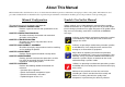
About This Manual This manual describes basic functions, theory of electrical and mechanical operations, maintenance and repair procedures of the printer. The instructions and procedures included herein are intended for the experienced repair technicians, and attention should be given to the precautions on the preceding page. Manual Configuration This manual consists of six chapters and Appendix. CHAPTER 1.PRODUCT DESCRIPTIONS Provides a general overview and specifications of the product. CHAPTER 2.
Revision Status Revision Issued Date A 2003/7/31 Description First Release
CONTENTS Disassembly and Assembly Overview......................................................................................................... 8 Precautions ............................................................................................... 8 Tools.......................................................................................................... 9 Work Completion Check..........................................................................
CHAPTER DISASSEMBLY AND ASSEMBLY
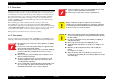
EPSON Stylus C63/64/83/84 Revision A 1.1 Overview W A R N IN G This section describes procedures for disassembling the main components of the Stylus C63/64/83/84. Unless otherwise specified, disassembly units or components can be reassembled by reversing the disassembly procedure. Things, if not strictly observed, that could result in injury or loss of life are described under the heading “Warning”. Precautions for any disassembly or assembly procedures are described under the heading “CAUTION”.
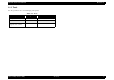
EPSON Stylus C63/64/83/84 Revision A 1.1.2 Tools Use only specified tools to avoid damaging of the printer. Table 1-1. Tools Name Supplier Parts No. Phillips Screw Driver (No.2) EPSON B743800200 Tweezer EPSON B741000100 Hexagon Box Driver (Opposite side : 5.
EPSON Stylus C63/64/83/84 Revision A 1.1.3 Work Completion Check Table 1-2. Work Completion Check Classification If any service is made to the printer, use the checklist shown below to confirm all works are completed properly and the printer is ready to be returned to the user. Table 1-2.
EPSON Stylus C63/64/83/84 Revision A 1.2 Caution regarding assembling/disassembling of the printer mechanism, and how to ensure of quality on re-assembled product On current low end models, we basically forbided to remove Housing (Lower) from Printer mechanism in your repair. This is because there is a possibility of main frame deformation when a part (such as Ink system) is removed from Printer mechanism without Housing (Lower).
EPSON Stylus C63/64/83/84 Revision A 1.3 Disassembly The flowchart below shows step-by-step disassembly procedures. When disassembling each unit, refer to the page number shown in the figure. Housing (Right/Left/Frame), Stacker assy.
EPSON Stylus C63/64/83/84 Revision A 1.3.1 Housing (Right/Left/Frame), Stacker Assy. removal [Housing (Right/Left/Frame) removal] 1) Releasing five hooks by hand/precision screwdriver (-), and remove Housing (Right). 2) Release one hook of I/F cover by inserting metal scale vertically from the slit on bottom of Housing (Left), and remove I/F cover.
EPSON Stylus C63/64/83/84 Revision A 3) Release Extension spring 0.585 for Paper return lever, and remove the lever with releasing two protrusions. 4) Release Compression spring 1.88 for Returd roller unit, and turn the roller unit until it is free. 1.3.2 ASF unit removal o External view Screw type : C.B.P-TITE, 3x8, F/SN Order of tightening : Third Thghtening torque : 6±1 kgf.cm o When assembling ASF unit, Screw type : C.B.S-TITE (P4), 3x6, F/SN Order of tightening : Second Thghtening torque : 8±1 kgf.
EPSON Stylus C63/64/83/84 Revision A o Removal procedure 1.3.3 Circuit board removal o External view Screw type : C.B.S TITE SCREW, 3x14, F/SN Order of tightening : First Thghtening torque : 8±1 kgf.cm Screw type : C.B.S TITE SCREW, 3x10, F/SN Order of tightening : Third Thghtening torque : 8±1 kgf.cm Screw type : C.B.S TITE SCREW, 3x6, F/SN Order of tightening : 4th Thghtening torque : 8±1 kgf.cm Screw type : C.B.S TITE SCREW, 3x14, F/SN Order of tightening : Second Thghtening torque : 8±1 kgf.
EPSON Stylus C63/64/83/84 A D J U S T M E N T R E Q U IR E D Revision A o When replacing the Main board with new one, perform the following service items. n If the read-out operation succeeds by adjustment program from defective main board, replace with new board and write the read out data to new one.
EPSON Stylus C63/64/83/84 Revision A o Removal procedure 1.3.4 Holder shaft unit removal o External view 1) Disconnect Panel board connector cable from the connector on main board, and remove Panel board. 2) Remove Clamp core from [Mounting Plate, M/B] and disconnect Head FFC, CR motor connector cable and PE sensor cable from the connector on main board. Then, release Head FFC and CR motor connector cable from Holder shaft unit. This marking is the hook/protrusion for releasing Holder shaft uni.
EPSON Stylus C63/64/83/84 Revision A n Make sure to place PE sensor cable to the suitable n Do not damage the tooth of Spur gear 36.8 and groove on LD roller shaft holder. Combination gear 27.2, 19.2. o When assembling Clutch mechanism to LD roller shaft, o When assembling Panel board to Holder shaft unit, (This operation is done after installing Holder shaft unit to main frame.) n Make sure to set the round hole of Clutch on the dowel of LD roller shaft.
EPSON Stylus C63/64/83/84 Revision A 1.3.5 PS board unit removal o When assembling the PS board to Shield plate (Lower) , o External view n Make sure to install the PS board correctly. Screw type : C.B.P-TITE SCREW, 3x8, F/SN Order of tightening : First Thghtening torque : 6±1 kgf.cm n Fasten four screws for securing PS board in the order / torque indicated in the figure. o When assembling Shield plate (Upper) to Shield palte Screw type : C.B.
EPSON Stylus C63/64/83/84 Revision A 1.3.6 CR motor removal o When assembling the CR motor to main frame, o External view n Do not damage CR motor pinion gear with main frame. Screw type : C.B.S TITE SCREW(P4), 3x6, F/ZN Order of tightening : non Thghtening torque : 8±1 kgf.cm n Make sure to connect the CR motor connector cable to Screw type : C.P SCREW, 3x4, F/ZN Order of tightening : First Thghtening torque : 4±1 kgf.cm the connector (CN5) on main board.
EPSON Stylus C63/64/83/84 Revision A 1.3.7 Paper guide upper removal C A U T IO N o External view o When removing/assembling Paper guide upper, avoid to damage the coated surface of PF roller by OHP sheet as the following figure. Paper guide upper OHP sheet Protrusion & Hook Figure 1-10. Paper guide removal procedure o When assembling Paper guide upper, Torsion spring, 60.05 n Make sure to install the tip of Torsion spring 60.05 in hole of Paper guide upper. Figure 1-9.
EPSON Stylus C63/64/83/84 Revision A 1) Return CR unit to home position before removing Front frame. 2) Remove two screws for securing Front frame to main frame. 3) Lift up the left side of Front frame slightly, and slide the frame toward the front side of the printer. 1.3.8 Front frame removal o External view Screw type : C.B.S TITE SCREW, 3x6, F/ZN Order of tightening : First Thghtening torque : 8±1 kgf.cm Screw type : C.B.
EPSON Stylus C63/64/83/84 Revision A 1.3.9 CR unit removal o External view (Cont.1) NOTE: "CR unit" described in this section means "IC holder with PW sensor/CR encoder sensor", "Print head assy.". Screw type : C.B.S TITE SCREW, 3x6, F/ZN Order of tightening : First Thghtening torque : 8±1 kgf.cm NOTE: The removal procedure for CR unit described in this section is as follows. Added operations before Front frame removal => Front frame removal => IC holder => Print head assy.
EPSON Stylus C63/64/83/84 Revision A o Part/Unit that should be removed before removing CR unit removal 11) Pull IC holder slightly to the front side of the printer, and remove CR unit from main frame. Housing (Right/Left/Frame) o Removal procedure C A U T IO N 1) Release CR lock lever toward the backside of the printer by the tweezer, and move CR unit from home position to around the center of the printer mechanism.
EPSON Stylus C63/64/83/84 Revision A o When assembling Print head assy., n Make sure that [Cap, Detector, PW] is correctly fixed. n Make sure that the CR timing belt is set in the o When assembling CR unit to main frame, assembling groove correctly. (CR timing belt is under hook of Print head assy..) n Make sure that main frame is located between [Roller n Do not stain the CR timing belt with the grease (G-58). n Make sure to install [Grounding Plate, Head] in the guide] and Print head assy..
EPSON Stylus C63/64/83/84 A D J U S T M E N T R E Q U IR E D Revision A o When you replace Holder pulley driven with new one, lubricate it with the suitable amount of G-65 grease by the specified position. A D J U S T M E N T R E Q U IR E D o When CR timing belt is removed or replaced with new one, tension adjustment of CR timing belt must be performed by the degital tension gauge.
EPSON Stylus C63/64/83/84 Revision A 1.3.10 Paper eject roller removal o When assembling Paper eject roller to main frame, o External view Pulley, PF, Driven n Do not touch the rubber portion. n Make sure that [Bushing, 6] is correctly fixed. Pulley, Eject, Driven Bushing, 6 n Do not damage the tooth of [Pulley, Eject, Driven] while PF timing belt is set. SPACER, 4.1x0.
EPSON Stylus C63/64/83/84 Revision A o Removal procedure 1.3.11 Paper guide front removal o External view 1) Remove one screw for securing Paper guide front to main frame, and remove Paper guide front with pulling the left side of Paper guide front slightly. Porous Pad, Paper guide front Screw type : CBS TITE SCREW, 3x6, F/Zn Order of tightening : First Thghtening torque : 8±1 kgf.cm C A U T IO N o Do not touch the rib of Paper guide front and [Porous Pad, Paper guide, Front].
EPSON Stylus C63/64/83/84 Revision A o Part/Unit that should be removed before removing Printer mechanism/ 1.3.12 Printer mechanism/Housing (Lower) removal Housing (Lower) o External view Housing (Right/Left/Frame) / ASF unit / Circuit board / PS board / CR unit with Front frame / Paper eject roller / Paper guide front Screw type : C.B.P-TITE SCREW, 3x8, F/Zn Order of tightening : Third Thghtening torque : 6±1 kgf.
EPSON Stylus C63/64/83/84 Revision A o When assembling Printer mechanism to Housing (Lower), n On this models, the assembed accuracy of each part composed of Printer mechanism is based on Housing (Lower). To ensure the assembled accuracy, you have to control the assembled standard position of main frame against X/Y/Z-axis direction as the following figure. [X-axis direction] - Make sure that main frame is correctly placed on the groove of Housing (Lower).
EPSON Stylus C63/64/83/84 Revision A n Do not touch the sealing rubber portion and the Cleaner n Make sure that Cap unit moves smoothly. head of the Cap unit. n Do not damage Change lever and Combination gear, n Make sure that [Sheet, Protect, Splash] is correctly 27.2, 19.2 by dropping. pasted on Cap unit. If the adherence of [Sheet, Protect, Splash] is lower, replace it with new one to avoid that ink leak out of printer. n Make sure that ink tube is connected on joint tube area of cap frame.
EPSON Stylus C63/64/83/84 Revision A 1.3.13 Ink system removal o When assembling Ink system, o External view n Do not touch the sealing rubber portion and the Cleaner head of the Cap unit. Combination gear, 21.24 Change lever n Make sure that line mark on ink tube is not twisted. Pump unit n Make sure that ink tube is connected on joint tube area Spur gear, 27.2 Cap unit of cap frame. Compression spring, 2.36 n Make sure that Cap unit moves smoothly. Combination gear, 27.2, 19.
EPSON Stylus C63/64/83/84 Revision A 1.3.14 PF motor removal C A U T IO N o External view Screw type : HEXAGON NUT, NORMAL, M3 Order of tightening : First Thghtening torque : 6±1 kgf.cm Screw type : HEXAGON NUT, NORMAL, M3 Order of tightening : 4th Thghtening torque : 6±1 kgf.cm o When removing PF motor from main frame, do not damage the pinion gear of PF motor. o When assembling PF motor to main frame, n Do not damage PF motor pinion gear with main frame.
CHAPTER ADJUSTMENT
EPSON Stylus C63/64/83/84 Revision A 2.1 Overview This section describes the procedure for adjustments required when the printer is disassembled and assembled for repair or service. *175+0) 2.1.1 Required Adjustment If you remove or replace the specific part in your service/repair, you have to perform the appropriate adjustment as listed Table 5-1 below.
EPSON Stylus C63/64/83/84 Revision A Table 2-1.
EPSON Stylus C63/64/83/84 NOTE: Revision A “ “ ”: Required necessary adjustment ”: Only C83/C84 is required necessary adjustment. The numbers in the circle/square shows the required adjustment order. “NA”: Not applicable. • Platen Gap adjustment are not required on this product. • C63/C64 are not loaded with PW sensor, therefor you may not carry out PW adjustment. If using new main board in the printer mechanism replacement, you need to perform EEPROM initial setting of main board.
EPSON Stylus C63/64/83/84 Revision A NG pattern Sample for White Banding Sample for Black Banding Figure 2-6. PF Adjustment Pattern 2 2.1.5 PW Adjustment 1)Set Economy Photo Paper A4 on the Paper Support. 2)Print the PW sensor adjustment check pattern, choose the pattern number 5mm away from each edge, and enter it in the adjustment program. Figure 2-4. Bi-D Adjustment Pattern3 2.1.4 PF Adjustment 1)Set Super Fine Photo Paper A4 on the Paper Support. 2)Select PF adjustment in the adjustment program.
EPSON Stylus C63/64/83/84 Revision A 2.1.6 First Dot Adjustment 1)Set Economy Photo Paper A4 on the Paper Support. 2)Print the First Dot adjustment check pattern, It adjusts so that it may be set to 3±1.5mm away from each edge. 3±1.5mm Figure 2-8. First Dot Pattern 2.1.7 Top Margin Adjustment 1)Set Normal Paper A4 on the Paper Support. 2)Print the Top Margin adjustment check pattern, It adjusts so that it may be set to 3±1mm away from each edge. Figure 2-10. A4 Normal Print 3±1mm Figure 2-9.
CHAPTER MAINTENANCE
EPSON Stylus C63/64/83/84 Revision A 3.1 Overview 3.1.2 Service Maintenance If any abnormal print (dot missing, white line, etc.) has occurred or the printer indicates the "Maintenance request error" (This error is displayed as "Maintenance call error" in the STM3), take the following actions to clear the error. This section provides information to maintain the printer in its optimum condition. 3.1.
EPSON Stylus C63/64/83/84 1. Revision A Select the “EPSON Status Monitor 3” in the printer driver utility, and make sure that the printer is in stand-by state by using the Status monitor 3. If the printer is in stand-by state, the following figure is indicated on the monitor. o Maintenance request error (Maintenance call error) Ink is used for the printhead cleaning operation as well as the printing operation.
EPSON Stylus C63/64/83/84 Revision A 3.1.3 Lubrication Table 3-2. Lubrication point The characteristics of the grease have great affects on the mechanical function and durability, especially does the characteristics about temperature environment. The type and amount of the grease used to lubricate the printer parts are determined based on the results of the internal evaluations.
EPSON Stylus C63/64/83/84 Revision A Table 3-2. Lubrication point No. 4 5 6 Lubrication type/point Table 3-2. Lubrication point Remarks No. • Lubricate G-58 along CR guide parts of [FRAME MAIN] on 4 position by using Frame main lubrication fixture. (Figure 3-7) • G-58 • Quantity for each position is 100mg. • Length of G-58 spread is 350mm. (From Paper Guide Front to Slider Cap hook) • Wide of G-58 spread is 2mm.
EPSON Stylus C63/64/83/84 Revision A Lubrication area with G-58 (350 mm length) Lubricate with G-46 on 2 position of shafts Figure 3-5. Lubrication point 2 1 2 3 [FRAME,MAIN] Lubrication position : 4 positions 4 G-58 Profile (right side view) of CR guide position of [FRAME,MAIN] Figure 3-7. Lubrication point 4 Lubrication of G-58 : Ø 1 X 0.5 Ø 35 mm Length of lubrication area of G-58 20 mm Figure 3-6. Lubrication point 3 Figure 3-8.
EPSON Stylus C63/64/83/84 Revision A [HOLDER,PULLEY,DRIVEN] G-26 : Ø 1 X 1 mm Figure 3-9. Lubrication point 6 G-65 Ø1mmX1mm G-58 : Ø 1 X 1 circle Figure 3-11. Lubrication point 8 PULLEY,EJECT,DRIVE;B Figure 3-10.
CHAPTER APPENDIX
EPSON Stylus C63/64/83/84/ Revision A 4.1 Electrical Circuits 4.2 Parts List The electric circuit diagrams below are shown at the following pages: This Service Manual has not indicated Part List. Please refer to Service Part Information in Tech Exchange about Part List.
EPSON Stylus C63/64/83/84/ Revision A Figure 4-1.
EPSON Stylus C63/64/83/84/ Revision A Figure 4-2.