
Service manual


REV.-A
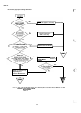
5.4 Repairing the Board Assembly, C094 MAIN
This section provides instructions for repairing the BOARD ASSEMBLY,
C094
MAIN. It describes various
problems, symptoms, likely causes, checkpoints, and solutions. The checkpoint column provides proper
waveforms, resistance values, and other information for each component of the
C094
MAIN.
Table 5-5. Repairing the BOARD ASSEMBLY,
C094
MAIN
Problem
Symptom
Cause
Checkpoint
Solution
Abnormal
The CPU
The reset
Check the voltage waveforms of the VDD (+5
Replace
IC4.
Dperation
at
does not
circuit is
V)(IC4
pin 41) and ROUT
(IC4
pin 15) when the
power on.
operate defective.
power is turned on.
properly.
?
-1
-
(CHl:Power)
!
m
A
1
I I I I I I
1
II
I
I
I
I
I
I
1
II
Ill
I
1
I
[1
1
I
I
I
I
1
II
I I I
1
1
T
1
+
CH1=2V
CH2=2V
TIME=O.
IS
[
1 1
)
1
I
The control
Check the signal HIGH/LOW alternation
(IC4
Replace
IC4.
ROM is not
pin 4).
selected.
CHI=2V TIME=lps
!
I
I
1
1
Either the
Replace IC2
ROM
or the
or
IC3.
RAM
is
defective.
f“
.+
5-14