
Service manual


REV.-A
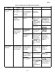
A.1 Connector Summary
Figure A-1 illustrates the interconnection of the primary components.
Table A-1 summarizes the functions
and sizes of the connectors.
BOARD ASSEMBLY,
C076 PSB/PSE
I
I
BOARD ASSEMBLY, C094 MAIN
CN1
I
IDETEC;”R’PG1
IEF-1
I
I
I I
DETECTOR, ‘E
(Front)
1
~
PRINTHEAD
1
&
PRINTER MECHANISM
—
I
—
BOARD ASSEMBLY,
C094
PNL
Figure A-1. Cable Connections
A-1