
Service manual


REV.-A
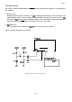
2.3.4 Carriage Motor Drive Circuit
The carriage motor drive circuit controls the CR motor. An open loop, constant current drive arrangement runs
the CR motor. 2-2 and 1-2 phases are used to excite the motor. A 2-2 phase step is equivalent to a 1-2 phase
step doubled. Table 2-5 describes the motor drive modes.
The CR motor drive circuit of the
SLA7024M
(IC6)
detects and regulates the amount of current flowing in the
carriage motor coil. The current flowing through the coil varies depending on the speed of the CR motor. The
CPU sets the amount of current via the l/O port of the gate array. Signals are sent to the ports (L, M, HOLD)
on the
SLA7024M. The SLA7024M sets the coil current depending on the CR motor speed.
The printer may stop printing to protect the CR motor from overheating if a continuous printing of short
columns (less than 10 columns) is repeated.
The printer uses CPU ports
P60
to
P63
exclusively to control the CR motor.
CPU
(IC2C1)
P60
P61
P62
P63
E05A66YA
(IC4)
G
PC4
Data
PC5
Bus
PC6
Speed mode
4/3
9/8
1
5/6
2/3
1/2
5/1
2
1/4
5/24
1/8
INA
CRA
INB CR-A
IN-A
CRB
IN-B
CR-B
LOW
MIDDLE
HOLD
Gp
MOTOR
1
ASSEMBLY, CR
r --------- . --.-----,
I
I
8
1
[
8
i
1
I
lqfp-1
1
I
I
t
1
1
,
I
t
1
,
1
I
1
1
I
I
8
1
1
1
IL
L
------------------
A
CRCOM
l-l
<CR MOTOR>
4-ph,
200-P HB type pulse motor
1
GiD
35VDC
+8Y0
-7~o
5.4Sh10Y0
(per phase) (at 25 ‘C)
Figure 2-27. Carriage Motor Drive Circuit
Table 2-6. Carriage Motor Drive Modes
PPS
4468
3840
3357
2800
2240
1680
1400
840
700
420
Excitation phase
2-2
2-2
2-2
2-2
2-2
1-2
1-2
1-2
1-2
1-2
Characters printed
Superdraft
Superdraft
copy
Draft 10 cpi
4/3 High duty
NLQ
5/12 High duty
1/4 High duty
2-27