
Service manual


REV.-A
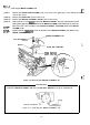
3.2.5 Removing the PRINTER MECHANISM
[STEP 11
[STEP 21
[STEP
31
[STEP 41
[STEP 51
[STEP 61
[STEP 71
Remove the PAPER GUIDE ASSEMBLY, top cover, front cover, paper eject cover and tractor unit.
(See Section 3.2.1.)
Remove the PANEL UNIT. (See Section 3.2.2.)
Remove the HOUSING ASSEMBLY, UPPER. (See Section 3.2.4.)
Remove the four
CBB
(M4X12) screws securing the PRINTER MECHANISM.
Remove the CBS
(M3X6)
screw securing the INTERFACE COVER.
Disconnect the following connectors on the BOARD ASSEMBLY,
MAIN:
CN3
(2-pin#
Blue)/
CN4
(2-
pin, White),
CN5
(2-pin, Black),
CN6
(6-pin),
CN7
(2-pin, yellow),
CN8
(ld-pinh
CN9
(S-pin)r
CN12
(lO-pin), and CN13 (5-pin).
Remove the PRINTER MECHANISM.
CBB
(M4X12)
h
+
I?’’CBS(M3X6)
1
la
‘\
~
INTERFACE COVER
&
PRINTER MECHANISM
.,
‘9
Figure 3-7. Removing the PRINTER MECHANISM
3-9