
Service manual


REV.-A
3.2.5.4
Removing the MOTOR ASSEMBLY, PF
[STEP 11
Remove the PAPER GUIDE ASSEMBLY, top cover, front cover, paper eject cover and tractor unit.
(See
Section 3.2.1.)
[STEP
21
Remove the PANEL UNIT. (See Section 3.2.2.)
[STEP 31
Remove
the HOUSING ASSEMBLY, UPPER. (See Section 3.2.4.)
[STEP 41
Remove the PRINTER MECHANISM. (See Section 3.2.5.)
[STEP 51
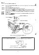
Set the LEVER, RELEASE to the vertical or forward position.
[STEP 61
Remove the FFC cables and then the two CBS
(M3X8)
screws
securing the
MOTOR ASSEMBLY,
PF.
[STEP 71
Remove the MOTOR ASSEMBLY,
PF.
*This position does not release
LEVER POSITIONS
the MOTOR ASSEMBLY,
PF.
RELEASE
ASSEMBLY, PF
CBS
(M3X8)
/
Figure 3-12. Removing the MOTOR ASSEMBLY, PF
3-13