
Service manual


REV.-A
3.2.5.5
Disassembling the GEAR TRAIN, PF
,.
[STEP 1]
[STEp
21
[STEp
31
[STEP 41
[STEP 51
[STEP 61
[STEP 71
[STEP 81
Remove the PAPER GUIDE ASSEMBLY, top cover, front cover, paper eject cover and tractor unit.
(See Section 3.2.1.)
Remove the PANEL UNIT. (See Section 3.2.2.)
Remove the HOUSING ASSEMBLY, UPPER. (See Section 3.2.4.)
Remove the PRINTER MECHANISM. (See Section 3.2.5.)
Remove the MOTOR ASSEMBLY, CR. (See Section 3.2.5.3.)
Remove the MOTOR ASSEMBLY, PF. (See Section 3.2.5.4.)
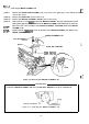
Remove the
FFC
cables from the FRAME, SUB, RIGHT of the PRINTER MECHANISM, and then
remove the two CBS
(M3X8)
screws
securing the FRAME,
SUB,
RIGHT.
Remove the FRAME, SUB, RIGHT.
‘1
FFC
Cables
CAM, CLUTCH, TRACTOR
Figure 3-13. Disassembling the GEAR TRAIN, PF
Assembly Note
Be sure to properly mesh the LEVER, RELEASE with the mechanism.
8-
--!
f:...’
Figure
3-14,
Positioning the LEVER, RELEASE for Insertion
3-14