EPSON 32KB Serial Interface Card C82307 * C823088 * English Deutsch Français Español Italiano 4000273 C01-00
FCC COMPLIANCE STATEMENT FOR AMERICAN USERS This equipment has been tested and found to comply with the limits for a Class B digital device, pursuant to Part 15 of the FCC Rules. These limits are designed to provide reasonable protection against harmful interference in a residential installation. This equipment generates, uses, and can radiate radio frequency energy and, if not installed and used in accordance with the instructions, may cause harmful interference to radio communications However.
2KB Serial Interface Card C82307* / C82308* English 32-KB-Schnittstellenkarte C82307* / C82308* Deutsch Carte d´Interface série 32Ko C82307* / C82308* Français Módulo de interface en serie de 32KB C82307* / C82308* Español Scheda dell´interfaccia seriale da 32KB C82307* / C82308* Italiano
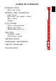
TABLE OF CONTENTS SETTING THE CONDITIONS Card layout DIP-switch and jumper settings DIP switches Jumpers 2 3 4 4 5 5 14 DATA ENTRY Serial communication About data entry Handshaking protocol 16 16 16 17 SELF TEST Loopback mode Line-monitor mode 21 21 22 SPECIFICATIONS 23 HARDWARE DESCRIPTION 25 CIRCUIT DIAGRAMS 28 INSTALLATION 31 INTRODUCTION About this guide
INTRODUCTION The Serial Interface Card C82307 * /C82308 * is an interface that allows asynchronous serial data communication between a host computer and an EPSON printer.
About this guide This guide is designed to give you detailed information on how to install your C82307 * /C82308 * serial interface card in a variety of EPSON printers. Installation procedures vary slightly depending upon the printer model that you have. Also included are instructions on how to adjust the settings of the C82307 * /C82308 * interface card, as well as a general description of serial data communication.
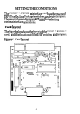
SETTING THE CONDITIONS The C82307 * /C82308 * interface card has three sets of DIP (Dual In-line Package) switches, and eight jumpers. These switches and jumpers are used for selecting various interface operations. Card layout The figure below shows the layout of the C82307 * KS2308 * card, and the locations of the DIP switches and jumpers. Figure 1.
DIP switch and jumper settings Before you install the C82307* /C82308* interface, you may need to adjust the DIP-switch 2, DIP-switch 3, and jumper settings. You can change the DIP-switch 1 settings after you install the interface. When making DIP-switch setting changes, it is best to use a pointed device, such as a ball-point pen or small screwdriver. Caution All changes of DIP-switch and jumper settings should be made with the printer power turned off.
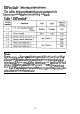
DIP switch 1 (interface operations) The tables below contain information on switch functions, and the factory setting of each. Table 1. DIP switch 1 Note Some printers have a selecting switch (or function) that allows you to select between the optional and original interfaces. If you install the interface card in this type of printer, you should set DIP switch 1-l on the interface card to ON and also change the setting in the printer to select the optional interface.
Data word structure The data word structure is also operator selectable through DIP-switch settings (See Table 1). The word structure for serial data is: 1 start bit +7 or 8 data bits (selectable) + 1 parity bit (selectable) + l or more stop bits. The table below shows the possible word structure combinations. Table 2. Word structure You can select the parity check method with DIP-switch settings (See Table 3). Table 3.
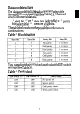
DIP switch 2 (interface operations) The tables below contain information on switch functions, and the factory setting of each. Table 4.
Baud rate selection In serial data communication, data is transmitted in the form of bits. These data bits go out one at a time along a single path, and in a specified order. The BPS (Bits Per Second) rate, or speed at which these bits are transmitted, can be selected using a combination of DIPswitch settings. Note In either RS-232D or Current-Loop mode, accurate data transfer cannot be guaranteed at a baud rate exceeding 19,200 BPS. Table 5.
Handshaking selection and Interface selection The table below shows the relation between handshaking selection and interface selection. Table 6. Handshaking and interface Note • In RS-422A mode, selecting DTR handshaking outputs the DTR flag through the DTR pin (No. 20); selecting X-on/X-off handshaking, fixes the value of the DTR • The signal is always in a fixed, flag reset state. Signal polarity can be inverted with DIP switch 3-4.
Table 7. Handshaking protocol selection Table 8.
DIP switch 3 (Interface operation) The tables below contain information on switch functions, and the factory setting of each. Table 9.
Note • Buffer full recovery timing (DIP switch 3-2 and 3-3) and DTR flag set/X-off transmit timing (DIP switch 3-6) selections are enabled only when buffer operation is enabled (DIP switch 3-1 is OFF). If SW3-1 is ON, buffer full recovery timing is set to 32 bytes and DTR flag set/X-off transmit timing is set to 16 bytes. • DSR/DCD signals (DIP switch 3-5) are enabled when RS-232D is selected.
Jumpers The jumper is a small terminal used for connecting or disconnecting a circuit. The jumper is on when the jumper plug covers both wires of the terminal. Jumper settings can be changed by either attaching or removing the rectangular jumper plug. If the jumper is to be turned off, connect it to just one of the two terminal pins as shown in the figure below. By doing this, you can avoid losing the unused jumper plug. Figure 2.
Table 11. Jumper settings Note • If the host computer is not equipped with a power supply for the Current-Loop interface, jumpers Jl, J2, and J3 must be connected for communications via the Current-Loop interface. • When Current-Loop is selected, see the section on circuit diagrams to determine the correct current source and current return. • J5, J6, and J7 jumpers are connected at the factory; you should not change these settings.
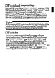
DATA ENTRY This section gives a brief description of serial data communication conditions and handshaking protocols supported by the C82307* /C82308* interface card. Serial data communications The C82307* /C82308* interface allows you to select either RS-232D, RS-422A, or 20-mA Current-Loop signal levels for data communication. This interface card also provides for either DTR (Data Terminal Ready) or X-on/X-off handshaking protocol.
Handshaking protocol X-on/X-off Protocol X-on/X-off protocol is a system in which the printer transmits a code to the computer to indicate that it cannot accept more data, and a second code when it is once again ready. This protocol can be performed under either RS-232D, RS-422A, or 20-mA Current-Loop signal levels. The C82307* /C82308* interface card sends an X-on (11H) code when it is ready to receive data, and an X-off (13H) when it is busy.
• Transmit timing of the X-on signal The X-on signal is transmitted when the power is first turned on, and when the vacant area in the buffer is greater than the preset value of the buffer recovery timing. Refer to Table 12 for information on flag set/reset conditions. Figure 3. X-on/X-off timing X-ON POWER ON X-OFF Buffer capacity: 512 or 16 bytes X-OFF Buffer capacity 0 byte X-ON Buffer capacity specified with DIP switches 3-2 and 3-3.
With the status flag set and data reception prohibited, the vacant area of the buffer gradually increases as the printer continues to print. When the vacant area for bytes reaches the preset recovery value (see Table 12), the flag is reset and data entry is again enabled. Buffer Operation Disabled Under this condition, the flag is output from the DTR (pin No. 20) in the case of RS-232D, from the TRA and TRB (pin No. 11, 13) in the case of RS-422A, and from the TTY-TXD (pin No.
Flag set timing is selectable with DIP switch 3-6, and flag reset timing is selectable with DIP switches 3-2 and 3-3. Printer status error The flag is set immediately, regardless of the remaining buffer capacity, if the printer detects an error.
SELF TEST Two self-test modes can be selected by DIP switches 3-7 and 3-8. To select a self-test mode, first turn off the power to the printer and then change the DIP-switch setting. When the power is turned back on, the new settings automatically go into effect. To exit from the self test, turn off power and reset the DIP switches. Table 13.
Line-monitor mode During this test, data on the RS-232D line, RS-422A line, or Current-Loop line is printed in hexadecimal code. The only difference between normal operation and this mode is that all data is converted into hexadecimal form.
SPECIFICATIONS 1. Synchronization: Asynchronous 2. Baud Rate: RS-232D: 75, 110, 134.5, 150, 200, 300, 600, 1,200, 1,800, 2,400, 4,800, 9,600, or 19,200 BPS (selectable) RS-422A: 75, 110, 134.5, 150, 200, 300, 600, 1,200, 1,800, 2,400, 4,800, 9,600, 19,200, or 38,400 BPS (selectable) Current Loop: 75, 110, 134.5, 150, 200, 300, 600, 1,200, 1,800, 2,400, 4,800, 9,600, or 19,200 BPS (selectable) 3.
5 . Handshaking Table 15. Handshaking Using DTR protocol Using X-on/X-off protocol RS-232D The signal at pin No. 20 is Data transmitted from pin as follows; No. 2 is controlled as MARK-data transfer follows; disabled X-on (11H)—data transfer SPACE-data transfer enabled enabled X-off (13H)—data transfer disabled (Signal polarity can be inverted by DIP-switch setting.) RS-422A The signal at pin No. 11 with respect to pin No.
HARDWARE DESCRIPTION 1. I/F board connector: EIA standard 25-pin D-SUB female connector. 2. For signal description and pin assignment, refer to the table below: Table 16.
26
Note The column heading “Direction” refers to the direction of signal flow as viewed from the printer.
CIRCUIT DIAGRAMS RS-232D Transmitter/Receiver Circuit Diagrams Figure 4. Transmitter Circuit Diagram l/3 MC145407 TXD From TXD l/3 MC145407 DTR From DTR Figure 5.
RS-422A Transmitter/Receiver Circuit Diagrams Figure 6. Transmitter Circuit Diagram Figure 7.
Current-Loop Transmitter/Receiver Circuit Diagrams Figure 8. Transmitter Circuit Diagram Figure 9. Receiver Circuit Diagram Note Set Jumpers J1, J2, and J3 referring these diagrams.
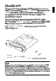
INSTALLATION The C82307* /C82308* interface card is designed to be installed inside the printer. Installation or removal of the interface card is easy, and requires only a screwdriver. The following section gives you detailed information on how to install your interface card in a variety of EPSON printers. Caution • Turn off the power to the printer and the computer before installing the interface card. Make sure that all power and interface cables are removed.
2. Fit both sides of this interface card into the guides inside the compartment. 3. Insert this interface card until the interface pins mate with the connector inside your printer. 4. Secure the interface with the two screws.
EPSON OVERSEAS MARKETING LOCATIONS EPSON AMERICA, INC. 2780 Lomlta Blvd., Torrance. Calif. 90505. U.S.A Phone: (213) 539-9140 Fax: (213) 534-5854 EPSON DEUTSCHLAND GmbH Zülpicher Straße, 4000 Düsseldorf 11 F.R. Germany Phone: (0211) 56030 Telex: 8584786 EPSON UK LTD. Campus 100, Maylands Avenue. Hemel Hempstead, Herts, HP2 7EZ, U.K. Phone: 442-61144 Telex: 5162467 EPSON FRANCE S. A. 68 bis, rue Marjolin 92300, Levallois-Perret, France Phone: (1) 47-373333 Telex: 610657 EPSON AUSTRALIA PTY. LTD.