EPSON 32KB Parallel Interface Card C82310 * English Deutsch Français Español Italiano 4000402 S01-00
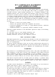
FCC COMPLIANCE STATEMENT FOR AMERICAN USERS This equipment has been tested and found to comply with the limits for a Class B digita1 device, pursuant to Part 15 of the FCC Rules. These limits are designed to provide reasonable protection against harmful interference in a residential installation. This equipment generates, uses, and can radiate radio frequency energy and, if not installed and used in accordance with the instructions, may cause harmful interference to radio or television reception.
2KB Parallel Interface Card C82310* 32-KB-Schnittstellenkarte C82310* Carte d’Interface parallèle 32Ko C82310* Módulo de interface en paralelo de 32KB C82310* Scheda dell’interfaccia parallela da 32KB C82310*
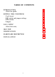
TABLE OF CONTENTS SETTING THE CONDITIONS Card layout DIP switch and jumper settings DIP switches Jumpers 2 3 4 4 5 5 7 DATA ENTRY About data entry 9 9 SELF TEST 10 SPECIFICATIONS 11 HARDWARE DESCRIPTION 12 INSTALLATION 15 INTRODUCTION About this guide 1
INTRODUCTION The Parallel Interface C82310* is an interface card that allows parallel data communication between a host computer and an Epson printer.
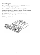
About this guide This guide tells you how to install your C82310* interface card in a variety of Epson printers. Also included are instructions on how to adjust the settings of the C82310* interface card, as well as a general description of parallel data communication.
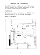
SETTING THE CONDITIONS The C82310* interface card has two sets of DIP switches, and five jumpers. These switches and jumpers are used for selecting various interface operations. Card layout The figure below shows the layout of the C82310* card and the locations of the DIP switches and jumpers. Figure 2.
DIP switch and jumper settings Before you install the C82310* interface, you may need to adjust DIP switch 1 and jumper settings. You can change switch 2 settings after you install the interface. When making DIP-switch setting changes, use a pointed device such as a ball-point pen or small screwdriver. Caution Always turn the power off before changing DIP-switch and jumper settings. New settings take effect when the printer is turned back on.
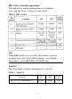
DIP switch 1 (interface operations) The table below contains information on switch functions, and the factory setting of each switch. Table 1. DIP switch 1 Note When DIP switch l-l is set to ON, the interface card can continue store data in the buffer memory even though the printer is in an OFF LINE or PAUSE state. Switch 2 The table below contains information on switch 2. Table 2.
Some printers have a switch (or function) that allows you to select between the optional and original interface. If you install the C82310* interface card in this type of printer, set the interface card’s DIP switch 2 to ON and also change the setting in the printer to select the optional interface. Jumpers A jumper is a small plug used for connecting or disconnecting a circuit. The jumper is on when the jumper plug covers both wires of the terminal.
The tables below describe the interface conditions that can be selected using jumpers. In all cases, ON means you connect the jumper (cover both terminals), while OFF means you disconnection of the jumper. Table 3. Jumper settings Jumper Function J1 Fixed (See Note) J2 Fixed (See Note) J3 Fixed (See Note) J4 Fixed (See Note) JG ON: Connect chassis ground to signal ground Factory setting OFF Note Jl,J2,J3, and J4 jumpers are connected at the factory; do not change these setting.
DATA ENTRY About data entry For quick data entry, the C82310* interface card is equipped with a buffer that temporarily stores data before it is printed. When this buffer becomes full, the interface card send a BUSY signal . (Reception of data during this state cannot be guaranteed.) The data in the buffer is automatically sent to the printer when the printer indicates it is ready to accept more data.
SELF TEST You can run the self test by first turning off the printer and then turning on DIP switch l-3. When you turn the power back on, the self test begins. To exit from the self test, turn off the power and turn DIP switch 1-3 off. The interface card first checks the RAM condition. After checking the RAM, data from <30>H to <39>H is sent to the printer and printed (the printout is only 80 columns wide). Table 4. Self-test mode Note It takes some time to check the RAM before test printing beings.
SPECIFICATIONS 1. Data transmission: 8-bit parallel 2. Synchronization: External supplied STROBE pulse 3. Handshaking: Via ACKNLG or BUSY signals 4. Logic level: TTL level 5. RAM capacity: 32 Kbytes 6. Connector: 57-30360 (Amphenol), 36 pin or its equivalent Interface timing The figure below shows the timing for the parallel interface. Figure 3.
HARDWARE DESCRIPTION For signal description and pin assignment, refer to the table below: Table 5. Signal description and pin assignment Signal Pin Return Pin Signal Direction 1 19 STROBE IN The STROBE pulses to read data. Pulse width must be more than 0.5 µseconds at the receiving terminal. 2 3 4 5 6 7 8 9 20 21 22 23 24 25 26 27 DATA 1 DATA 2 DATA 3 DATA 4 DATA 5 DATA 6 DATA 7 DATA 8 IN IN IN IN IN IN IN IN These signals represent data in bits 1 to 8 of parallel data, respectively.
Signal Pin Return Pin Signal Description Direction 13 SLCT OUT A high signal indicates that the printer is in the selected state. The signal goes low in the following cases: 1) When the SLCT IN signal goes high 2) During a printer-error state 3) When the interface card is disabled This signal can be fixed to “high” with DIP Switch 1-5. 14 AUTO FEED XT IN This function depends on printer specifications.
Signal Return Pin Pin Signal OUT 35 36 SLCT IN Description Direction IN Pulled up to +5 V through 3.3 K W resistance. The DC1/DC3 code are valid only when this signal is high. (This signal can be fixed low by changing a DIP switch, jumper, or SelecType setting on the printer.) The printer monitors this signal, so this signal’s function depends on the printer’s specifications. Note • The column heading Direction refers to the direction of signal flow as viewed from the printer.
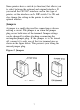
INSTALLATION Installation or removal of the C82310* interface card is easy, and requires only a screwdriver. The following section tells you how to install your interface card in a variety of EPSON printers. Caution • Turn off the power to the printer and the computer before installing. Make sure that all power and interface cables are removed. • Avoid touching the printer’s circuit board contacts; many components are sensitive to static electric charges that may build up on your body. 1.
3. Insert firmly until the interface pins mate with connector inside your printer. 4. Attach the two screws to secure the interface.
EPSON OVERSEAS MARKETING LOCATIONS EPSON AMERICA, INC. 20770 Madrona Avenue Torrance CA 90503, USA Phone: (213) 782-0770 Fax: (213) 782-5248 EPSON DEUTSCHLAND GmbH Zülpicher Straße 6, 4000 Düsseldorf 11 F.R. Germany Phone: (0211) 56030 Telex: 8584786 EPSON UK LTD. Campus 100, Maylands Avenue Hemel Hempstead Herts. HP2 7EZ, UK Phone: 442-61144 Telex: 5182467 EPSON FRANCE S. A. 68 bis. rue Marjolin 92300. Levallols Perret, France Phone: (1) 4087-3737 Telex: 610657 EPSON AUSTRALIA PTY. LTD.
EPSON Printed in Japan 91.