EPSON TERMINAL PRINTER EPL-5600 ActionLaser 1600 SERVICE MANUAL .
NOTICE All rights reserved. Reproduction of any part of this manual in any form whatsoever without SEIKO EPSON’s express written permission is forbidden. The contents of this manual are subjects to change without notice. All efforts have been made to ensure the accuracy of the contents of this manual. However, should any errors be detected, SEIKO EPSON would greatly appreciate being informed of them.
PRECAUTIONS Precautiomry notations throughout the text are categorized relative to 1) personal injury and 2) damage to equipment. DANGER Signals a precaution which, if ignored, could result in serious or fatal personal injury. Great caution should be exercised in performing procedures preceded by DANGER Headings. WARNING Signals a precaution which, if ignored, could result in damage to equipment.
SAFETY INFORMATION This printer is a page printer which operates by means of a laser. There is no possibility of danger from the laser, provided the printer is operated according to the instructions in this manual provided. Since radiation emitted by the laser is completely confined within protective housings, the laser beam camot escape from the machine during any phase of user operation. For United States Users; [Laser Safety] This printer is certified as a Class 1 Laser product under the U.S.
VAROITLJS Laitteen Iciiyttiminen muulla kuin tiissd Idiytt50hjeessa mainitulla tavalla saattaa altistaa ldiyttiijiin turvallisuusluokan 1 ylittiiv~lle niikyrniitt&r@le Iasersiiteiylle. VARNING Orn apparaten anviinds pi% annat siitt ti i denna bruksanvisning sp-ificerats, kan anvtidaren utstittas fdr osynlig laserstrihin~ som 6verskrider grhser for laser klass 1.
For Europe / LASER KLASSE 1 NACH IEC 825 CLASS 1 LASER PRODUCT TO IEC 825 KLASSE 1 LASER PRODUKT I.H.T. IEC 825 .w \ [Label inside printer] The following laser safety label will be attached inside the printer as shown below.
PREFACE This manual describes functions, theory of electrical and mechanical operations, maintenance, and repair of EPL-5600 /ActionLaser 1600. The instructions and procedures included herein are intended for the experience repair technician, and attention should be given to the precautions on the preceding page. The chapters are organized as follows: CHAPTER 1. GENERAL DESCRIPTION Provides a general product overview, lists specifications and illustrates the main components of the printer. CHAPTER 2.
REVISION SHEET Revision Rev. A Revision Page Issue Date Februaty 2, 1994 1st issue i - . .
TABLE OF CONTENTS CHAPTER 1. CHAPTER 2. CHAPTER 3. CHAPTER 4. CHAPTER 5. CHAPTER 6. APPENDIX GENERAL DESCRIPTION OPERATING PRINCIPLES DISASSEMBLY AND ASSEMBLY ADJUSTMENTS TROUBLESHOOTING MAINTENANCE - ,..
. Chapter 1 General Description Table of Contents 1.1 FEATURES .. 1-1 1-3 1.2 SPECIFICATIONS 1.2.1 Basic Specifications. . . . . . . . . . . . . . . . . . . . . . . . . . . . . . . . . . . . . . . . . 1-3 1.2.2 Electrical Specifications. . . . . . . . . . . . . . . . . . . . . . . . . . . . . . . . . . . . . . 1-5 1.2.3 Reliability Specifications . . . . . . . . . . . . . . . . . . . . . . . . . . . . . . . . . . . . . 1-5 1.2.4 Environmental Conditions for Operating (including Imaging Cartridge). .
1-33 1.5 MAIN COMPONENTS 1.5.1 C125 MAIN Board . . . . . . . . . . . . . . . . . . . . . . . .‘. . . . . . . . . . . . . . . . . 1-34 1.5.2 C82326* l/F Board (Optional LocalTalk Module). . . . . . . . . . . . . . .‘. . . 1-35 1.5.3 Control Panel.... . . . . . . . . . . . . . . . . . . . . . . . . . . . . . . . . . . . . . . . . . 1-35 1.5.4 PWB-A Board.... . . . . . . . . . . . . . . . . . . . . . . . . . . . . . . . . . . . . . . . . . 1-36 1.5.5 pWB-E Board.... . . . . . . . . . . . . . . . . . . . . . .
List of Tables Table 1-1. Options for EPL-5600 and ActionLaser 1600 . . . . . . . . . . . . . . . . . 1-2 Table 1-2. Paper Feed Methods. . . . . . . . . . . . . . . . . . . . . . . . . . . . . . . . . . . . 1-3 Table 1-3. Paper Types . . . . . . . . . . . . . . . . . . . . . . . . . . . . . . . . . . . . . . . . . . 1-3 Table l-4. Usability ofSpecial Papers . . . . . . . . . . . . . . . . . . . . . . . . . . . . . . . 1-4 Table l-5. Electrical Specifications. . . . . . . . . . . . . . . . . . . . . . . . .
EPL-5600/ActionLaaer 1600 Service Manual eeneral Deac@ion 1.1 FEATURES The Epson @ EpL.5600 and the ActionLaser TM 1600 are non-impa~ page pMterS that ~rnbine a semi-conductor laser with electro-photographic technology. These printem are small and lighc and feature high-speed, high-resolution printing. Maintenance is very easy as a result of various built-in diagnostic functions.
EPL46W/ActionLaser 1600 Service Manual General Description Table l-l lists the optional units available for the EPL-5600 and ActionLaser 1600. Table 1-1. Options for EPL-5600 and ActionLaser 1600 Machine Type Cat. No.
General LM.scription EPL-5600 /ActionLaser 1600 Service Manual 1.2 SPECIFICATIONS This section provides statistical data for the EPL-5600 and ActionLaser 1600. 1.2.
EPL-6600/ActionLaser General Description 1600 Service Manual See Table 1-4. Usability of special papers: Table 1-4. Usability of Special Papers Input output OHP Envelopes Labels Card Stock Letterhead Standard built-in paper tray Face down P P P P R Face up R R R R R Lower paper cassette Face down Face up N N N N P N N N N P R: Reliable feeding and good image quality. P: Possible, but better avoided. N: Not supported.
General Description EPL-5600 /ActionLaser 1600 Sawice Manual 1.2.2 Electrical Specifications Table 1-5.
EPL4i600/ActionLaser General Description 1600 Service Manual 1.2.6 Applicable Standards Safety Standards 120 VAC model: 220/240 VAC model: UL 1950, CSA 22.2 N0.
General ascription EPL4600 IActionLaser 16tM Service Manual 1.2.9 Software Specifications HP LaserJet 4 emulation (pCL@ Se) EPSON GL/2 mode (LJ4-GL/2 mode and GL-like mode) FX (FX-670/1170, LX-1OO) emulation mode ESC/P 2 (LQ-570/1070) mode Built-in modes: Note: The EPSON GL/2 mode is similar to the GL/2 mode included in the HP LaserJet 4 emulation. Table 1-6 shows the differences between EPSON GL/2 mode and the GL/2 mode in the HP LaserJet 4 emulation.
EPL-5600/ActitmLaser General Descrit2tion 1600 Service Manual Table 1-7.
EPL-5600 /ActionLaser 1600 Service Manual General Description Font Symbol Sets HP LaserJet 4 Mode (bitmap fonts): 15 symbol sets Roman-8 Roman Extension ECM94-1 ANSI ASCII French2 Legal IBM@-US PcMultilingual Norwegl Italian Swedis2 LJK German Spanish IBM-DN HP LaserJet4 Mode (scalable fonts): 34 symbol sets Ronam-8 Italian Swedis2 UK German 8859-2 1S0 PsMath WiTurkish VeMath Math-8 PcTk437 PsText IBM-DN PcMultilingual VeUS PcE.
EPL-5600 /ActionLaser 1600 Service Manual General Description 1.3 INTERFACE SPECIFICATIONS The EPL-5600 and ActionLaser 1600 are equipped with the following external interfaces: ■ Parallel interface ■ RS-232C/RS-422 interface ■ Optional LocalTalk interface ■ Optional Type B interface 1.3.1 Parallel Interface The parallel interface has two modes as follows: S Compatibility mode (same as parallel interface of EPSON’s current page printer) ■ Reverse mode 1.3.1.
EPL-561W/ActionLaser 16tW Service Manual General Description Table 1-8. Parallel Interface Pin Assignment Pin No. 1 STROBE Vo Description IN STROBE is a strobe pulse used to read data from the host computer. The pulse width must be more than 0.5 psec. Normally it is HIGH, and data is latched at the trailing edge of this signal. DATA 1-8 IN 10 ACKNLG OUT 11 BUSY OUT The BUSY signal informs the host computer of the printer state. When the signal is HIGH, the printer cannot accept data.
EPL-5600/ActionLaser 1600 Service Manual General Description 1.3.1.2 Reverse Mode The reverse mode for EPL-5600/ActionLaser 1600 supports the nibble mode of IEEE-P1284. This printer can run in reverse mode, in which the printer can inform the computer of its status by EJL and PJL commands. System: Nibble mode of IEEE-P1284 Connector type: P90-25027-1 (Amphenol) receptacle Applicable plug: 57-30360 (Amphenol or equivalent) Signal description: See Table 1-9. Table 1-9.
Generai Description EPL-5600 /ActionLaaer 1600 Service Manuai Figure 1-4 shows the parallel interface state switch diagram. o- Compatibility Mode 1 1O”s Q TROBE Forward Data Transfer Forward ACK and BU~Y A SLCT IN=HIGH ERR=HIGH Terminate Idle Failed Negotiation No data sent SLCT IN= LOW ERR= LOW Sending data I ER R= LOW Sending data AUTO FEED = LOW Request to send data AUTO FE ED= LOW AUTO FE ED=HIGH FRR=LOW Figure 1-4. Parallel Interface State Switch Diagram Rev.
EPL-5600/ActionLaser 1600 Sarvice Manual General Description Figure 1-5 shows the timing chart of negotiation. x - , OOh or 04 h DATA SEL-IN STROBE AUTO-FEED ACKNLG Peripheral Busy Status BUSY PE ~ Current Peripheral $tatus / \ ; \ I Note 2 i \ ; —. SLCT ERROR ~ Current Peripheral Status / Notel u A,A — Notel : Negotiation Compatibility ; 1 h,A — HB DA or : Idle or Transfer HB DNA (Note 3) Figure 1-5.
Ganaralihactipthn EPL-5600 /ActionLaaar 1600 Service Manual Figure 1-7 shows the timing chart of termination. DATA SEL-IN STROBE N o t e 3 ~—~ AUTO-FEED ACKN LG ,/ BUSY Peripheral Busy St~lus / PE . SLCT Note 2 ERROR Note ,., -, ...... Note 1 ; 1 I HB DNA, Idle, or HB DA 1 \ Peripheral Busy Status ; Current Peripheral Status I Current Peripheral Status \ / H : b- Termination Compatibility Figure 1-7. Timing Chart of Termination Note 1: The signal is HIGH when FIB DNA.
EPL-6600/ActionLaser 1600 Service Manual General Description 1.3.
EPL-S600 /ActionLasef 1600 Sewice Manual General Lhwetiption Note 1: ( ) indicates an R%122 signal, which is SPlecType. Note 2: “CT’S’, “DSR”, and “DTR” states can be selected through SelecType. Note 3: Although the signals RTS, Cl%, DSR, Dl% and DCDare RS-232C level, they can be used for RS-422 mode if selected through SelecType. Note 4: SD+, SD-: Serial ASCII data output from the printer. HIGH level; when SD+ voltage is higher than SD-voltage. LOW level; when SD+ voltage is less than SD- voltage.
EPL4600/ActionLaser 1600 Service Manual General Description 1.3.3 Optional LocalTalk Interface This printer can use the optional LocalTalk interface module. Signal level: Protocol: LocalTalk Same as 179422 signal level X-ON/X-OFF (cannot be combined with DTR control) DTR control (cannot be combined with X~N/X43FF) Transfer speed: 230.4 K bps Signal description: See Table 1-11. Type: Table 1-11. LocalTalk Interface Pin Assignments Pin No.
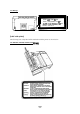
General Lhwctiption EPL-5600 /ActionLaser 16tW Servkw Manual 1.4 OPERATING INSTRUCTIONS ,f%??> ,f.w:.: ~.y This section desaibes the functions performed through the control panel, such as test print, hexadecimal dump, and SelecType functions. 1.4.1 Control Panel The printer control panel gives you easy control over most common printer operations. ‘Me panel consists of a liquid aystal display (LCD), indicator lights, and buttons. SelecType Item Menu u On Line mu Tti$::SW3 ....... . . . . . . . . . .
General Description EPL&6001ActionLaser 1600 Service Manual Buttons ■ ON LINE ■ Manual (ON LINE + ALT) ■ ITEM ■ Paper Size (ITEM+ ALT) Enters SelecType mode. Changes the item in SelecType mode. Enters directly (short cut) to the paper size setting of the standard and optional paper tray in PRINTING MENU of SelecType. (MENU+ ALT) Enters SelecType mode. Changes the menu @ SelecType mcde. Enters directly (short cut) to the paper tray select setting in CONFIG MENU of SelecType.
Generai Wription EPL-66(W/ActionLaser 1600 Sendce Manuai 1.4.2 SelecType Functions The SelecType function on the printer control p~el allows the user to control most of the printer’s functions, su&I as printing test pages, selecting a paper size, and changing the printer’s configuration. Enter SelecType mode by pressing the MENU or ITEM button. Table 1-12 shows the SekcType options. Tabie 1-12.
EPL4600/ActionLaser 1600 Service Manual General Description Table 1-12. SelecType Functions (Cont.) Menu (Chan M & M E N U ! ESCP2 (Cont.) FX GL2 1-22 Available Options (Chan ad by ~or ~ button) (Set%y ENTER button) (Chang~ t!~~EM button) Auto CR ON, OFF Auto LF ON, OFF Zero Char o, ($ Bit Image Dark, Light, BarCode Font Courier, Prestige, Orator S Pitch 10 CPI, 12 CPI, 15 CPI, Prop Condensed ON, OFF T-Margin 0.40 to 1.50 Inch (step 0.
Ganerai ~ription EPL6600 /ActionLaaar 16U0 Sarvica Manual Table 1-12. SelecType Functions (ContJ (Chan Available Options (Chan ad b ~or~ button) (Sat%y EdTER button) Menu W MENu (chang~ $~EM button) r utton) JOI3 EMULATION PAGE PROTECT OFF, LT, LGL, A4 RESOLUTION 300,600 TIMEOUT 5 to 300 PARALLEL LJ4, FX, ESCP2, PS*, GL2, PMLJ4*, PS&FX*, PS&ESCP2*, PS&G12* SERIAL LJ4, FX, ESCP2, PS*, GL2, PS&LJ4*, PS&FX*, PS&ESCP2*, PS&GL2* LJ4, FX, ESCP2, PS*, GL2, PS&LJ4*, PS&FX*, PS&ESCP2*, PS&G12 ;.
EPL-5600/ActionLaser 1600 Service Manual General Description Table 1-12. SelecType Functions (Cont.
General Desor@ion EPL-66@lActionLaser 16iUl Servke A&mud 1.4.3.3 Factory Service Mode The factory service mode is a useful tool fir service people. This mode is not available to users. To enter factory semice mode, turn on the printer while holding down the ON LINE and CONTINUE buttons until “PRODUCT MENU” is displayed. The factory service settings are shown in Table 1-13. Table 1-13. Factory Service Mode Menu (Chang~~~)MENU PRODUCT NAME TCOUNT I TCOUNTCLEAR PCOUNT PCOUNT CLEAR I JCOUNT <...
EPL-5600/ActionLaser 1600 Service MAnual General Description 1.4.4 Display of Messages This printer displays three types of messages on the LCD: status messages, error messages, and power on messages. 1.4.4.1 Ststus Messages The LCD panel normally indicates the printer’s status and the software mode. Table 1-14. Status Messages status Message SELF TEST RESET ALL Internal self test Warm txwt RESET Resetting SelecType is changed while Form Feed light is on. Press the RESET button to reset.
General Dssctipmn EPL-5600 /ActbnLasar 16(M SeWce Manual Table 1-15. Emor Messages (Cont.) I I Message I status REMOVE CART Cartridge was insetted while Form Fed light was on or the printer was on line. RAM ERROR (Note) Either the SIMM is damaged or it is not supported. EEPROM ERROR EEPROM data error. SERVICE REQ. Xxxxx Printer problem. Note: I Msasuree Remove cartridge and press CONTINUE button. Power off and then remove SIMM. I press the CONTINUE button. Service required.
EPL4600/ActionLaser 1600 Service Manual General Descrbtion 1.4.5 Printer Sharing This section describes printer sharing. This printer has two methods of printer sharing, port fixed mode and auto sense mode. These modes are selected by SelecType menu “AUTO SENSE”. 1.4.5.1 Port Fixed Mode When the printer is in port fixed mode, only one interface port is active. Data from other ports is ignored.
G@lerai IMacd@k?n EPL-5600/ActionLaser 16tM Service Manuai 1.4.5.2 Auto Sense Mode It is possible to allocate each mode to parallel, serial, L/T, and ALJX. ‘l’he entire memory will be allocated to the channels that are used. The intert%ce that receives the data first will print first. . Mode Assignment HP mode ESCIP2 mode 4 FX mode Parallel User 1 GL2 mode EpsonScript mode ) Mode Assignment ESC/P2 mode El- Serial User 2 ‘--- Input buffer \ . GL2 mode EpsonScript mode ,-.
EPL-5600/ActionLaser 1600 Service Manual General Description 1.4.6 Emulation Mode Switch Function This section describes the emulation mode switch function. 1.4.6.1 Emulation Switch by SPL The two types of emulation switch functions described below are available on this printer. Together they are referred to as SPL (Shared Printer Language). EJL: EPSON Job Language This is EPSON’s original language system. It is able to skip among various destinations, as shown in Figure 1-12.
Geneml lhscd@on EFi-5600 /ActkmLaser 16(XI Sendc8 U%nual 1.4.7 Bi Resolution improvement Technology The EPL-5600/ActionLaser 1600 printers have BiRiTech @i Resolution Improvement t Technology), which is designed to improve print quality at 6MI dpi and 300 dpi. By this method, the dot map data extracted from the image data is reassembled to impmve print data. The main improvement of this technique is in eliminating “jaggies” in diagoml lines.
General Description EPL-561W/ActionLaser 1600 Service Mhnual 1.4.8 Optional Memory If you have difficulty printing complex, graphics-intensive pages or if you regularly use downloaded fonts, you may need to install the optional SIMM sets on this printer’s controller board. The printer’s controller board comes with 2.0 MB of RAM installed. By installing additional SIMMS, you can increase the printer’s memory to a total of 64 MB, including the resident memory.
EPL+600/ActionLaser 1600 Servke Manual GensralLhscdptbn 1.5 MAIN COMPONENTS To simplify maintenance and repair, the main components of the EPL-5600/Actionbser 1600 have been designed for easy removal and replacement.
EPL-6600/ActionLaser 16(70 Service Manual General Description 1.5.1 C125 MAIN Board The C125 MAIN board is a video controller board. The primary functions of this board are receiving print data from the host, generating the print image (video), and sending the print image to the engine controller via the video interface. A 32-bit 17.6 MHz RISC CPU MB86930 (SPARKlite) (location: IC1) is used, and the following memory chips and custom ICS are assigned to the 4 GB memory space.
EPL4WM /Ac~ 16W Sorvko Manual GenemIlhecdpuon 1.5.2 C8232M I/F Board (Optionai LocaiTaik Module) The C8232f# I/F board has the LocalTalk interfam arcuit, which allows this printer to mnnect to Apple” Maantosh” computers. l’he LocalTalk Module is available for a LocalTalk mmwctkm. ■ Main Chips 85C30 (IC3) 26T.530 (ICI) 26LS32 (1(2) NJU7660 (IC4) 26LS31 (1:1) r v f NJU7660 (K%) ..* : +.:. , / I 9 * a 9 * ,,; , / ● ● ● * . . . a. . . . .C ● - - - * - - -* 8 9 * , *--, , .
EPL-5600/ActionLaser 1600 Service Manual General Descri~tion 1.5.4 PWB-A Board This is the engine controller board. It consists ofanM37451M48-bit CPU (including a MASK ROM) and a gate array. The board controls laser scanning (the polygon mirror drive motor), image synchronization, laser beam pulse width, and power. I I “,.lfl ~M37451 M4 Figure 1-20. PWB-A Board 1.5.5 PWB-E Board The PWB-E is the power supply board, which consists of a switching regulator circuit.
EPL-56W /Ac#mLaser 16tM SeWlce Manual Genrnlhwxiption 1.5.6 PWB-F Board The PWB-F is the high-voltage supply circuit board. It converts the development bias, OPC drum charge bias, and image transfer bias. Do not touch VRIF and VR2F on ths PWB-F boani. These volunass am~ factory ssth”ng only. ❑ o c1 ,. . .. . I Ii31 VRIF VR2F ❑ ‘L. . . . Figure 1-22. PWB-F Board 1.5.
General Description EPL4600/ActionLaser 16(W Service Manual 1.5.8 Fusing Unit The fusing unit fixes the toner to the paper using heat and pressure. This unit has a heater lamp, thermistor, and thermal fuse. There are two types of fusing units, the 120 V type and the 220/240 V type. The only difference between them is the heater lamp. 1.5.9 Drive Unit The drive unit consists of the main motor and a series of gears and clutches.
EPL-661W/ActionLsser 16(X) Servioa Manual General Description 1.5.11 Lower Paper Cassette The optional lower paper cassette allows you to feed up to an additional 250 sheets of A4 or letter-size paper into this printer. Figure 1-27. Lower Paper Cassette 1.5.12 Face-Up Output Tray The face-up output tray is an optional tray useful for feeding single sheets of paper types, such as envelopes, transparencies, labels, or heavy paper.
Chapter2 Operating Principles Table of Contents 2.1 ENGINE OPERATION 2“1 2.1.1 Print Process. . . . . . . . . . . . . . . . . . . . . . . . . . . . . . . . . . . . . . . . . . . . . . 2-2 2.1.1.1 Paper Feeding. . . . . . . . . . . . . . . . . . . . . . . . . . . . . . . . . . . . . . . 2-3 2.1.1.2 Drum Charge. . . . . . . . . . . . . . . . . . . . . . . . . . . . . . . . . . . . . . . . 2-4 2.1.1.3 Laser Exposure.. . . . . . . . . . . . . . . . . . . . . . . . . . . . . . . . . . . . . 2-5 2.1.1.
List of Figures Figure 2-1. Main Components. . . . . . . . . . . . . . . . . . . . . . . . . . . . . . . . . . . . . . 2-1 Figure2-2. Print Process Diagram . . . . . . . . . . . . . . . . . . . . . . . . . . . . . . . . . . 2-2 Figure2-3. PaperFeedingfrom the Multi-Purpose Tray. . . . . . . . . . . . . . . . . . 2-3 Figure2-4. PaperFeedingfrom the Lower PaperCassette . ..............2-4 Figure2-5. Drum Charge . . . . . . . . . . . . . . . . . . . . . . . . . . . . . . . . . . . . . . . . . 2-4 Figure2-6.
EPL-6600 /&#onLaser 161W S4wvJce Manunl OpWathg Princlpbs 2.1 ENGINE OPERATION This section describes the functions and operating pMciples of the EPL-56W, ActimLaser 1600 engine. Figure 2-1 shows the locations and names of the main engine mmponents. 6 12345 7 9 8 10 11 12 13 14 15 16 18 19 20 21 29 1. 2. 3. 4. 5. 6. 7. 8. 9. 10. 11. 12. 13. 14. 15.
EPL-5600/ActionLaser 1600 Service Manual Operating Principles 2.1.1 Print Process This section describes the print process from paper feeding to paper exit. Figure 2-2 shows a diagram of the print process. i—-—- —- — -- Fusing 6. 7. Toner ::; Q!Elm-’, 6“ 2. Brush Charging D. /’ 3~ \ i w% m.!”;, ‘L - - . —-—-—.- ./ -/” Imaging Cartridge -—. —- —. —.#l’– 1. Paper Feeding 1 —-—.—-—.—-—-—-—-—- 1. Figure 2-2. Print Process Diagram 2-2 Rev.
EPL-6600 /ActionLaser 161W Service Menual Opwatig Princ@ee 2.1.1.1 Paper Feeding There are two methods of feeding the paper into the printer. One is by using the multi-purpose tray (standard tray), and the other is by using the optional 25kheet lower paper cassette. Paper~ut conditions are detected by the paper empty sensor, located above the paper tray or the cassette. While paper is in the tray or cassette, the detection lever for the paper empty sensor is lifted.
Operating Principles EPL-5600/ActionLaser 1600 Service hfhual Lower Paper Cassette A maximum of 250 sheets can be loaded in the 250-sheet lower paper cassette (option). The cassette must be capable of handling the paper size, however. (The lower paper cassette unit can hold letter or A4 paper.) The driving force for paper feeding and transport is from the transmission gear. All electrical controls are performed on the printer side through the coupling comector. Ca Paper te Figure 2-4.
Opwating Rincfpha EFL4i6(MlActionbaar 16W Sarvlca h4hnua/ 2.1.1.3 Laser Exposure Laser exposure is the process of creating an invisible static electric image on the PC drum with laser beams emitted from the optid unit. The mirror motor (scanner motor) rotates the six+ided mirror counterclockwise to produce a laser light scan. (One side of the mirror produces one scan.
EPL-561W/ActionLaser 1600 Service Manual Operating Principles 2.1.1.6 Image Transfer Image transfer is the process of transferring the toner image created on the PC drum during the developing process to the paper. This printer uses the roller image transfer method, instead of corona image transfer, as the image transfer process. In roller image transfer, there is no generation of ozone as there is with corona discharge.
Opuating Prhc@laa EPL-5600/ActlonLaaer 161M Sarvka Manual 2.1.2 Engine Controi This section describes a@ne control, the power supply board, and the high-voltage supply board. The engine is controlled by the engine controller board (PWEA board). Figure 2-10 shows an engine ‘mntroller connecting diagram. PWB-D LD Sos Engine :~;;~ller , Mirror Scanner Motor --?. J“ . . . . . . .,<.~...
EPL-56tW/ActionLaser 1600 Service Mimual Operating Principles 2.1.2.1 Main Motor Functions and Control Power from the main motor (Ml) drive is used for the P/C (photo conductor) drive, the developing drive, the fusing drive, the standard paper slot feeding drive, and the lower paper cassette (option) feeding drive. Figures 2-11 through 2-16 show the positions of the gears and rollers. 17 16 25 uAt3’1’ nr -#I Sleeve Roller I ~ ~lrnage Transfer Roller ..— —- . w 2 1 ● 23 ● 22 ● 24 “26 Fig.
Opadng Iwdpbs EIUWIM /llcfionLaser 161X? 6orvico R&mud Table 2-1. Geara and Rollera No. of Gear Teeth No. No.
EPL-5600/ActionLaser 1600 Service Manual Operating Principles 2.1.2.2 Paper Take-Up Sensor and Paper Exit Sensor The paper take-up sensor has three functions: 1. To detect the top edge of paper. The engine starts printing when the detection signal is received. 2. To detect paper size. The printer detects the time it takes for paper to pass the paper take-up sensor during paper feeding. If this time is lon& longer paper is feeding; if the time is short, shorter paper is feeding. 3.
Optwathtg Principb8 EPL-56f30/ActionLaaar 16tM Sarvlca Manual The following fi~re shows the fuser temperature mmtrol procedure. Figure 2-20. Temperature for Fuser Control Procedure If the following renditions are detected, the printer indicates a fuser error (the LCD displays SERVICE REQ. EOO03). . The thermistor temperature dces not reach55° C (131° F) within 15 secmnds. . The warm-up period doesnotend within 120 seconds. ● The thermistor temperature drops to 130° C (266° F).
EPL-6690/ActionLaser 1600 Service Mhnual Operating Principles 2.1.2.5 laser Diode Drive Figure 2-23 shows the laser diode drive circuit. Laser diode emission is controlled by three signals (L DATA, DA1, and DA2) from the engine controller board (PWB-A). Laser Diode — S SCAN co DA2 DA1 LD Sos (PWB-D) \ SOS Mirror - b L DATA J SOS sensor Engine Controller Board (PWB-A) Figure 2-23. Laser Diode Drive Circuit The L DATA signal is the laser ON/OFF signal.
EPL-56W /Actkmbsef 16(M Se#Vke Mantd Opefating Fhc@&@s If the SCAN signal is not detected, the printer indicates a laser diode malfunction. If the scanner mirror motor (M2) does not rotate, the printer also indicates a laser diode ~“on. ~ Scanner Motor On LDATA 0.2 4 (CN5A-7) rsac.1 * SSCAN (CN5A-12) Figure 2-26. Laaer Diode Emor Detection 2.1.2.6 Biaa Voltagea and Laaer Drive liming ,> P \..
EPL-5600/ActionLaser 16(U3 Service Manual Operating Principles Figure 2-28 shows the print process, and Figure 2-29 shows the power on sequence. During the power on sequence (initialization), the printer detects mechanical errors. Brush Charging Laser Exposure Development Figure 2-28. Print Process Power On Fuser Temperature 130” C (266” F) 165” C (.329” F) Mirror Motor (M2) Main Motor (Ml) Drum Charge (CH1) Laser Exposure (LD) Development (DB) Image Transfer (CH1) Figure 2-29.
Opwating Prindplaa EPL-56W IActionLaaaw 161M Sarvica Manual Figure 2-31 is the end of the print sequence. The printer stops the main motor (Ml) from rotating when the paper exit sensor turns off after 2.53 seconds. Main Motor Off [sec.] y Paper Exit Senaor Off 1.27 Drum Charge (CH1) .8 1.26 b Laser Expoeure (LO) Development (DB] !t%%er (CH1 ) Figure 2-31. Print Sequence (End) 2.1.2.7 Fan Motor Control :... \ ..
EPL-5600/ActionLaser 1600 Service Manual Operating Principles 2.2 VIDEO CONTROLLER OPERATION The video controller section generates the video signals for the received data. The video controller section is separate in the C125 MAIN board and the control panel. The control panel is comected to the engine controller board (PWB-A), but is controlled by the C125 MAIN board, which sends the signals for the control panel through the engine controller board. Video Controller Section ,-------- ---------- . . . . .
O$uanng Ptinc@se EPL-561W/ActbnL8ser 16tM SetVke Menud Table 2-2 lists the functions of the C125 MAIN board main elements. Table 2-2. Functions of C125 MAIN Board Main Elements Element MB86930 RISC CPU ICI E05A91 ASIC IC9 E05A93 ASIC IC24 This ASIC contains the following fundions: . Video interface . Bi-Parallel interface ● RS-232C interface . RS-422 interface ● LocaiTaik module control ● Type-B interface card control .
EPL-6600/ActionLaser 1600 6ervice Manual Operating Principles Print data and commands transmitted from the host computer via parallel, serial, or optional interfaces are read using the interrupt process of the CPU and stored in the DIUM input buffer. Data and commands in the input buffer are processed by the CPU, which then stores the printing bitmap data (image data) in the V (video) -RAM (image buffer) in the DRAM. The size of the V-RAM depends on the available DRAM size.
Opwatfng Prindp+as EPL-5600 /ActionLaaar 16W Send@ Manual 2.2.1.1 Reset Circuit The entire system (the CPU and the external devices) can be initialized if the RESET signal (CPU pin 113) are active simultaneously. This circuit uses an h451938 IC to monitor the supply voltage if a voltage level less than 425 V is detected. The reset time is approximately 128 ma. +W +5V L + f . Vcc OUT RSTIN M51938FP (IC27) RSTOUT E05A92 (IC25) c L ~gure 2-38. Reset Circuit L ,. 2.2.1.
EPL-56(X?/ActionLaaer 16(M Service Mi#nua! Operating Principle 2.2.1.3 Interrupt Control The ASIC E05A93 determines the priority level of the interrupt and outputs it to terminals IRLO IRL3. Then an interrupt is sent to the CPU. When the IRLO-3 value is llllb, the CPU process is a non-maskable interrupt process. When the IRLO-3 value is OOOOb, the CPU process is a standard process. When the IRLO-3 is any other value, the CPU process is a maskable interrupt process. 2.2.1.
@uating P?inci#ea EP&56tM/ActionLaaar 16(XI SarV&a hfanwd 2.2.1.5 Parallal lnWfaceChwit Figure 2-41 shows the parallel intert%x anmit block diagram. Data sent from the host ~mputer is latched within the E05A93 by the SI’ROBE signal. The E05A93 outputs the BUSY signal automatically to stop the host computer from sending additional data. The CPU resets the BUSY signal after reading the data from the E05A93, so that the printer is ready to receive mom data from the host computer.
EPL-56001ActionLaser 161M Service Manual Operating Principles 2.2.1.7 RS-422 Circuit This circuit uses the RS-422 receiver/driver IC MC34050 (IC6) to change the signal level from the RS-422 signal level to the TTL signal level (O V or +5 V) or from the TTL signal level to the RS-422 signal level. The E05A93 standard cell changes serial (RS-422) data to parallel data. Serial Data Parallel Data Transmit . . . . . . . . . . ........
EPL-5600 /ActionLaser 1600 Sarvice Manual Oparating Principhw 2.2.1.10 Vidao Interface The ASIC E05A92 maps the SRAM into a memory space different from the system memory. The CPU transmits data from the V-RAM (in the system RAM) to the SRAM using the ASIC E05A92. The ASIC cell converts the image data in the SRAM from parallel to serial, synchronizes it, and then transmits it to the engine controller board.
? :, G ,%.’? ... ,., ’ - Chapter3 Disassembly and Assembly Table of Contents 3-1 3.1 GENERAL INFORMATION 3.1.1 Precautions for Disassembly/Assembly. . . . . . . . . . . . . . . . . . . . . . . . . . 3-1 3.1.2 TOOIS . . . . . . . . . . . . . . . . . . . . . . . . . . . . . . . . . . . . . . . . . . . . . . . . . . . . 3-1 3.1.3 Small Parts . . . . . . . . . . . . . . . . . . . . . . . . . . . . . . . . . . . . . . . . . . . . . . . 3-2 3.1.4 Sewice ChecksafterRepair . . . . . . . . . . . . . . . . . . . .
List of Figures Figure 3-1. Removing the Interface Cover . . . . . . . . . . . . . . . . . . . . . . . . . . . . 3-4 Figure 3-2. Removing the 3 Screws . . . . . . . . . . . . . . . . . . . . . . . . . . . . . . . . . 3-4 Figure 3-3. Pulling the Tab . . . . . . . . . . . . . . . . . . . . . . . . . . . . . . . . . . . . . . . . 3-4 Figure 3-4. Removing the Video Controller Board. . . . . . . . . . . . . . . . . . . . . .. 3-4 Figure 3-5. Removing the 2Screws . . . . . . . . . . . . . . . . . . . . . ........
Dieeaeemb/y and Aeeembiy EPL-56tW/ActionLaeer 161XJ Service M&nuai 3.1 GENERAL INFORMATION This chapter describes the disassembly/assembly procedures to be used for replaang the main assemblies of the EPL-5600/ActionLaser 16(X). 3.1.1 Precautions for Disassembly/Assembly Follow the precautions below when disassembling/assembling the printer. ■ Disconnect the power coni before disassemblinglassembling theprhter.
EPL-6600 /ActionLaser 1600 Service Manual Disassembly and Assembly 3.1.3 Small Parts In the followirw sections, abbreviations are used for small parts, such as screws and washers. Tables 3-2 and 3:3 list these abbreviations. Table 3-2.
LYsssssml#y sndAssetnb/y EPL-56LUI /ActionLsser 1600 Servics hhnunl 3.1.4 Service Checks after Repair e Check the repaired unit using the following list on completion of serviang. Tabie 3-4.
EPL4600 /ActionLaser 1600 Service Manual Disassembly and Assembly 3.2 DISASSEMBLY AND ASSEMBLY This section describes and illustrates the procedures for removing and disassembling the components of the EPL-5600/ActionLaser 16W. Cleaning is described in Chapter 6. The assembly procedures are not described, except for special notes where necessary, because assembly can be accomplished by performing disassembly in reverse. 3.2.
EPL-56U0/ActionLasar 16tM Sarvica Manual Dkiassambly and AssamMy 3.2.1.2 LocalTalk Module (C6232@ I/F Board) Removal 1. Remove the video controller board (C125 MAIN board). (Refer to Section 3.2.1.1.) 2. Remove 2 CP screws (M3 x5) from the LodTalk module. 3. Remove the LocalTalk module from thevideocontmller board (C125 MAIN board). CP (M3 X 5) — .>’= -.. Figure 3-5. Removing the 2 Screws ‘. *, :. . . . . Figure 3-6. Refi:;~~: the LocalTalk 3.2.1.3 Control Panel Removal 1. Open the top cover.
Disassembly and Assembly EPL-5600 /ActjonLaser 1600 Servjce Manual 3.2.2 Housing Removal This section describes how to remove the cases and the rear frame. 3.2.2.1 Case Removal 1. 2. 3. 4. 5. 6. 7. 8. 9. Remove the video controller board (C125 MAIN board). (Refer to Section 3.2.1.1.) Open the top cover. Remove the imaging cartridge. Cover the imaging cartridge to protect it from light or place it in a dark area. Remove the control panel. (Refer to Section 3.2.1.3.) Remove the paper cover.
Disassambiy and Assambiy EPf.-56OO /ActionLaser 1600 SeWbe Manuai 3.2.2.2 Rear Frame Removal 1. Remove thevideocontroller board (C125 MAIN board). (Refer to Section 3.2.l.l.) 2. Open the top cover. Remove the imaging cartridge. Cover the imaging cartridge to protect it from light or place it in a dark area. 3. 4. 5. 6. 7. 8. Remove the control panel. (Refer to Section 3.2.l.3.) Remove the paper cover. Remove the right cover and left cover. (Refkr to Section 3.2.2.l.) Remove the top cover.
EPL-5600/ActionLaser 1600 Service Manual Disassembly and Assembly 3.2.3 Disassembling the Engine This section describes disassembling the engine, including the engine controller board (PWB-A) and power supply board (PWB-E). 3.2.3.1 Engine Controller Board (PWB-A) Removal 1. Remove thevideocontroller board (C125 MAIN board). (Refer to Section 3.2.l.l.) 2. Open the top cover. Remove the imaging cartridge. Cover the imaging cartridge to protect it from light or place it in a dark area.
EPL-5600 /ActionLasar 16U0 Sanka Manual Dhassamb/y and Assambly 3.2.3.2 Power Supply Unit (PWB-E) Removal .,.,. -,. d 1. Open the top cover. Rerr&ve the imaging cartridge. Cover the imaging cartridge to protect it from light or place it in a dark area. 2. 3. 4. 5. Remove the control panel. (Re!%r to Section 3.2.13.) “ 6. 7. Remove the paper cover. Remove the right cover. (Refer to Section 3.2.2.l.
Disassembly and Assembly EPL4600/ActionLaser 1600 Service Manual 3.2.3.4 Optical Unit Removal ■ Do not touch the optical unit except at the time of replacement. 9 Do not open the unit under any conditions. ■ Do not remove the circuit boardfiom the optical unit under any condition. ■ Do not loosen the 2 screws that secured with a black paint (shown in position A in the figure). ■ Do not loosen the 2 screws (shown in position Bin the figure). Open the top cover. Remove the imaging cartridge.
EPL-5600 /ActionLasar 16(NI Servke Manual DkMssambly and Assambfy 3.2.3.5 Paper Empty Sensor Removal 1. Open the top cover. Remove the imaging cartridge. Cover the imaging cartridge to protect it from light or place it in a dark area. 2. Remove themntrol panel. (Retkrto%ction 3.2.1.3.) 3. Remove the paper cover. 4. Remove the paper guide case. (Retkr to Section 3.2.2.1.) 5. Remove thepowersupply unit. (Reikr to Section 3.2.3.2.) 6. Remove the optical unit. (Refer to Section 3.23.4.) 7.
Disassembly and Assembly EPL461W/ActionLaser 1600 Service Manual 3.2.3.6 High-Voltage Supply Board (PWB-F) Removal 1. Open the top cover. Remove the imaging cartridge. Cover the imaging cartridge to protect it from light or place it in a dark area. 2. Remove the control panel. (Refer to Section 3.2.l.3.) 3. Remove the paper cover. 4. Remove the right cover and left cover. (Refer to Section 3.2.2.l.) 5. Remove the top cover. (Refer to Section 3.2.2.l.) 6. Remove the rear frame. (Refer to Section 3.2.2.2.
DisassembiyandAssembiy EPL-5600 IActionl.aser 16tM Service Manuai 3.2.3.8 Fan Motor (Q Removal 1. Open the top cover. Remove the imaging cartridge. Cover the imaging mrtridge to protect it from light or place it in a dark area. 2. Remove the control panel. (Refer to Section 3.2.l.3.) 3. Remove the paper cover. 4. Remove therightcoverand Ieftcover. (Refer to Section 3.2.2.l.) 5. Remove the top cover. (Refer’ to Section 3.2.2.l.) 6. Remove the rear frame. (Refer to Section 3.2.2.2.) 7.
Disassemble and Assembly EPL-5600/ActionLaser 1600 Service Manual 3.2.3.10 Fusing Unit Disassembly This section describes how to remove the paper exit sensor, heater lamp, cleaning, lower fusing roller, and upper fusing roller. 1. Remove the fusing unit. (Refer to Section 3.2.3.9.) 2. Remove the paper exit sensor. 3. Remove 2 CC screws (M3 x 6) for the side covers, and remove the side covers. I I I I Do not touch the glass sutface of the lamp with your bare hands. 4.
EPL-5600 /ActionLaser 16(IO Sarvka Manual Disassembly and Assembly 3.2.3.11 hags Transfer Roller Removal 1. Open the top cover. Remove the imaging cartridge. Cover the imaging cartridge to protect it from light or place it in a dark area. 2. Remove the control panel. (Rei%rto Section 3.2.l.3.) 3. Remove the paper cover. 4. Remove the Ieftand right covers. (Refer to!%ction 3.2.2.1.) 5. Remove the top cover. (Refer to Section 3.2.2.l.) 6. Remove the rear frame. (Refer to Section 3.2.2.2.) 7.
Disassembly and Assembly EPL-5600/ActionLaser 1600 Service Manual 3.2.3.12 Paper Take-Up Roller Removal 1. Open the top cover. Remove the imaging cartridge. Cover the imaging cartridge to protect it from light or place it in a dark area. 2. Remove the control panel. (Refer to S@ion 3.2.1.3.) 3. 4. Remove the paper cover. Remove the left and right covers. (Refer to Section 3.2.2.l.) 5. 6. 7. Remove the top cover. (Refer to Section 3.2.2.1.) Remove the rear frame. (Refer to Section 3.2.2.2.
EPL-5tXM /ActionLasar 1600 Servka Manual DisassembtyandAssembly 16. Remove the roller cover. 17. Remove 1 E-ringon the paper take-up clutch, and remove the paper take-up clutch. 18. Remove 2 E-rings and left bushings on the paper take-up roller shaft. 19. Remove the paper take-up roller. Paper Take-Up Clutch Figure 3-24. Removing the Paper Take-Up Roiier Rev.
Chapter 4 Adjustment Table of Contents 4.1 ADJUSTMENT 4-1 4.1.1 Print Position Adjustment. . . . . . . . . . . . . . . . . . . . . . . . . . . . . . . . . . . . . 4-1 List of Figures Figure Figure Figure Figure 4-1. 4-2. 4-3. 4-4. Print Position Adjustment . . . . . . . . . . . . . . . . . . . . . . . . . . . . . . . . 4-1 Opening the Upper Unit, Paper Cover, and Removing 1 Screw. . . 4-1 Holding the Control Panel and Adjusting VRIA. . . . . . . . . . . . . . . .
A@atmeW EPL-56@ /ActkmLa~ 16(M Sarvke Manual 4.1 ADJUSTMENT @ This section describes the adjustment procedure for the EPL-5600 and ActicxLaser 1600. This adjustment must be performed after every servicing operation, especially when any component or part is replaod 4.1.1 Print Position Adjustment You can adjust the vertical print position on a sheet of paper by turning the image synchronizing volume control on the engine amtroller board (PWB-A).
Adjustment 6. EPL-5600/ActionLaser 1600 Service Manual While holding the control panel, adjust the image synchronizing adjustment volume (VRIA) on the engine controller board (PWB-A) so that the gap for the print position of the horizontal line (vertical print position) becomes 19.1 mm (0.75 inch) for EPL-5600 or 14.3 mm (0.56 inch) for ActionLaser 1600. ● Turn VRIA clockwise to decrease the gap for the print position of the horizontal line. ● Turn VRIA counterclockwise to increase the gap.
Chapter 5 Troubleshooting Table of Contents 5.1 OVERVIEW 5-1 5.2 SELF-DIAGNOSTIC FUNCTION 5-1 5.3 TROUBLESHOOTING TOOL 5-2 5.4 TROUBLESHOOTING 5-2 5.4.1 Troubleshooting of Abnormal Operation . . . . . . . . . . . . . . . . . . . . . . . . . 5-2 5.4.2 Print Quality Anomaly . . . . . . . . . . . . . . . . . . . . . . . . . . . . . . . . . . . . . . 5-12 List of Tables Table 5-1. Messages Requiring Semice Maintenance . . . . . . . . . . . . . . . . . . . 5-1 Table 5-2. Extension Cable . . . . . . . .
EPL-5600 IAc#onLaaer 161X) Sarvlca Manual T?oublaahoottng 5.1 OVERVIEW The EPL-56W and ActionLaser 16Ml have a sophisticated, built-in, selfdiagnostic function that reduces tmubkshooting time by identifying failed parts or components. This selfdiagrostic test overcomes the tmubkshooting problems for page printers, in which even a trivial failure can result in a serious print quality problem. 5.
EPL-5600/ActionLaser 1600 Service Manual Troubleshooting 5.3 TROUBLESHOOTING TOOL There is an extension cable provided for this printer to check the waveforms of the video controller board. You can remove the video controller board (C125 MAIN board) from the board slot and still check its waveforms by connecting the board to the engine with this cable. The following table shows the extension cable and comecting points. Table 5-2.
EPL46tM /ActionLaser 16(IO Service Manuaf Tmubkshooting Table 5-3. Symptoms and Reference Tables (Continued) Symptom Re~amlwce Printer Condition SERVICE REQ. COO03 The LCD displays SERVICE REQ. COO03. 5-21 SERVICE REQ. COO07 The LCD displays SERVICE REQ. COO07. 5-22 SERVICE REQ. C1OOO The LCD displays SERVICE REQ. C1OOO. 5-23 SERVICE SERVICE SERVICE SERVICE The LCD displays SERVICE REQ. Cl 110. The LCD displays SERVICE REQ. Cl 120. The LCD displays SERVICE REQ. Cl 130. REQ. REQ. REQ. REQ.
EPL&600/ActionLaser 1600 Service MAnual Troubleshooting Table 5-5. The Printer Does Not Start RAM Check I Cause The video controller board (C125 MAIN board) maybe dead. The control panel may be dead. Step Checkpoint Finding Solution 1 If you change the C125 MAIN board, does the printer starl the RAM check? Yes Replace the C125 MAIN board. 2 — Replace the control panel. — Table 5-6. The LCD Displays COVER OPEN cause The interlock switch terminal connector may be disconnected.
Troublaahooting EPL-56W/ActionLaaar 1600 Service Manual Table 5-9. The LCD Displays FEED JAM Cause step Checkpoint Finding Connector for paper take-up solenoid may be disconnected. 1 Is connector disconnected? Yes Connect it. Disconnect connector CN6 on the PWB-A board and check coil resistance between pin 7 and pin 8 on the disconnected cable side of the connector using a multimeter. Is the resistance approximately 80 ohms? No Replace the paper take-up solenoid.
EPL-5600/ActionLaser 1600 Service Manual Troubleshooting Table 5-10. The LCD Displays FEED JAM for Lower Paper Cassette Cause Step Checkpoint 1 Disconnect connector PJ2 on the lower paper cassette circuit board and check the coil resistance between pin 1 and pin 2 on the disconnected cable side of the connector using a multimeter. Is the resistance approximately 220 ohms? If the coil is shorted, check the solenoid drive circuit using the following procedure: 1. Set the multimeter to voltage. 2.
Ttvuble.etmtlhg EPL-66tW /ActionLaser 1600 Service Manual Table 5-12. The LCD Dispiays PAPER JAM during Paper Feeding checkpoint Finding Solution Is the imaging carttidge installed? No Install the imaging cartridge. Does paper always jam in paper take-up roller area? Yes Replace the paper take-up roller. e Does paper always jam in the image transfer roller area? ~= Replace the image transfer roller. 4 Does paper always jam in the fusing unit? ~= Repface it. - may be bad.
EPL4600/ActionLaser 1600 %rvice Manual Troubleshooting Table 5-16. The LCD Displays SERVICE REQ. EOO04 Cause The main motor coil may De open or shorted. The PWB-E board maybe dead. Step Checkpoint 1 Disconnect connector CN2 on the PWB-E board and check the coil resistance between: pin 1 and pin 2; pin 2 and pin 3; pin 4 and pin 5; and pin 5 and pin 6 (4 points total) on the disconnected cable side of the connector using a multimeter.
Tmubleshoofing EPL&61M IActionLaser 16(XI Service Manual Table 5-20. The LCD Displays SERVICE REQ. EO014 Finding Solution Cause Step The PWB-A board may M bad. The C125 MAIN board may , — — Replace the PWB-A board. 2 — — Replace the C125 MAiN board. be bad. Checkpoint Table 5-21. The LCD Displays SERVICE REQ. COO03 Cause Step The C125 MAIN boafd my be bad. 1 Checkpoint Finding Soiution — Replace the C125 MAIN board. — Table 5-22. The LCD Displays SERVICE REQ. COO07 .-. .
EPL4600/ActionLaser 1600 Service hhual Troubleshooting Table 5-27. The LCD Displays SERVICE REQ. C1140 Cause Checkpoint 1 Is the operation OK after you replace the ROM? — 2 — — The ROM (IC8) or (IC22) on the C125 MAIN board may be bad. The C125 MAIN board may be bad. Solution Finding Step Replace the ROM (IC8) or (IC22) on the Cl 25 MAIN board. Replace the C125 MAIN board. Table 5-28. The LCD Displays SERVICE REQ.
riw6&etJ@lng EPL-66@/ActionLaaer 16(M Sarv/ce Manual Table 5-33. The LCD Dispiays SERVICE REQ. C1200 of CI21O Cauee Checkpoint step The EEPROM (IC1O) on the C125 MAIN board my be bad. The C125 MAIN board my be bad. Finding 1 — — 2 — — Solution Replace the EEPROM OCIO) on I the C125 ~N “board. Replaoe the C125 MAIN board. Tabie 5-34. The LCD Dispiays SERVICE REQ. C1300 Cauaa Checkpoint Step Finding Solution The optional interface -fd 1 — may be bad. The C125 MAIN bMrd may be bad.
EPL-5600/ActionLaser 1600 Service Manual Troubleshooting 5.4.2 Print Quality Anomaly This section describes how to isolate a print quality problem from the possible causes. Table 5-38. Print Quality Anomaly Symptom .OW image density. ABCDE ABCDE ABCDE ABCDE Poor development Improper charging El Image transfer problem Imaging cartridge check the toner Ievei in the imaging cartridge. PWB-F board — Imaging cartridge — PWB-F board — ABCDE ABCDE ABCDE ABCDE n 5-12 Shake the imaging cartridge.
Troubleshooting EPL-56tXl/ActionLaser 1600 Sewica Manual Table 5-38. Print Quality Anomaly (Continued) Blank print Poor development Improper chargi D Poor image w transfer improper print dens”My setting Defective optical unit Black print Improper charging o Poor development Improper print density setting n Defective O@i@l unit WhitehIack lines and bands. ,4BC ,4BC ,4BC ,4BC Reinstall the imaging cartridge. PWB-F board — Replace the PWB-F board.
EPf.-56OO/ActionLaser 1600 Service Manual Troubleshooting Table 5-38. Print Quality Anomaly (Continued) Possible Cause Symptom \reas of missing wint Poor image transfer ‘4BCDE ABC’ : AP5LE AbCDE n Poor development Check ftem Part Name Remedy Check the surface RePla~e the i~ge Image transfer of the i~ge transfer roller. roller transfer roller. Replace the PWB-F PWB-F board — board. Shake the imaging — cartridge. Imaging cartridge Replace the imaging — cartridge.
Chapter 6 Maintenance Table of Contents 6-1 6.1 MAINTENANCE 6.1.1 User Maintenance . . . . . . . . . . . . . . . . . . . . . . . . . . . . . . . . . . . . . . . . . . 6-1 6.1.1.1 Cleaning . . . . . . . . . . . . . . . . . . . . . . . . . . . . . . . . . . . . . . . . . . . 6-1 6.1.1.2 Consumable Replacement . . . . . . . . . . . . . . . . . . . . . . . . . . . . . 6-2 6.1.2 Service Maintenance. . . . . . . . . . . . . . . . . . . . . . . . . . . . . . . . . . . . . . . . 6-3 6.1.2.
EPL&6tM/ActlonLaaer 16tM Servioe Manual Malntenanoa 6.1 MAINTENANCE The EPL-5&N and ActionLaser 1600 are page printers that use an electrophotographic printing method. Unlike with most impact or ink-jet printers, the key components in the electrographic process are integrated into an expendable cartridge (the imaging cartridge). l%ereiixe, pericxiic replacement of the imaging cartridge is essential to ensure high-quality output.
Maintenance EPL-5600/ActionLaser 1600 Service Manual 6.1.1.2 Consumable Replacement This printer uses consumable imaging cartridge SO51O16. The life of this cartridge is 6000 pages when printing on A4 or letter size pages with a 57. print ratio. If printed images become faint, remove the cartridge and gently shake it. This will distribute the toner and may make the images darker. If the image is still too light, replace the imaging cartridge.
Maintenance EFL46tM/ActionLaaar 16(M Service Manual 6.1.2 Sewice Maintenance This section describes the periodic service maintenance and cleaning required. 6.1.2.1 Periodic SeMce Maintenance The following units require periodic service maintenance because they are subject to functicxml deterioration as the total number of printed pages increase, resulting in bad print quality. Table 6-1. Periodic Service Maintenance Senfice Interval Unit Image Transfer Roller Approx. 100,OOO pages Approx.
Appendix A Reference Materials Table of Contents A.1 CONNECTOR PIN ASSIGNMENTS A-1 A.1.l Video Controller Board (C125 MAIN Board) . . . . . . . . . . . . . . . . . . . . . . A-4 A.1.2 Engine Controller Board (PWB-A Board) ._. . . . . . . . . . . . . . . . . . . . . . A-1 1 A.1.3 Power Supply Board (PWB-E Board) . . . . . . . . . . . . . . . . . . . . . . . . . . A-13 A.1.4 High-Voltage Supply Board (PWB-F Board) . . . . . . . . . . . . . . . . . . . . . A-13 A.2 CIRCUIT DIAGRAM A-15 A.
List of Tables Table A-l. Boarcj connector summary . . . . . . . . . . . . . . . . . . . . . . . . . . . . . . . A-3 TableA-2. CN3Pin A s s i g n m e n t s . . . - ” - . . ” ” - ” . . ” ” . ” . . “..”””o.o”-”.-” “A-4 Table&3.CN4Pin Assignments . . . . . . . . . . . . . . . . . . . . . . . . . . . . . . . . . . . .A-6 TableA-4. cN5Pin Assignments.-..- ...........-.”. .“o.-””s”-”..”. “A-7 TableA-5. CN6Pin Assignments..””. .....””-..”.... “.”.”.”..-””-.. -A-8 TableA-6. cN7Pin Assignments...”=. . . ” ” ” . - .
AppendixA EPL-6600 /ActionLaaw 16tM Sanfka Manual A.1 CONNECTOR PIN ASSIGNMENTS Figures A-1 and A-2 illustrate the interconnection of the primary components. Table A-1 gives the si= and a description of each connector. Video Controller Board -.. .............. GN” 1 Parallel l/F 1 CN; . Serial UF C82326* W Beard ,, E ‘,, HP font cartridge ............. .& ● , ● ● ● * * , , ● , * ● ● ● ............ . CN3 1 * 9 * * 9 0 * . . . . . . . . . . . . . .
EPL-6600/ActionLaser 1600 Service Manual Appendix A -z U* %C Ju L1l-1 FmI G& 1 . n. I QJ m o z. >.Z =: ~m L–__. –_. __. J < Figure A-2. Cable Connections for the Engine Section A-2 Rev.
EPL&6(M /ActionLaser 161Xl Service Manual AmandhA Table A-1.
EPL-6600/Act]onLaser 1600 Serv]ce Manual Afwendix A A.1.l Video Controller Board (C125 MAIN Board) Table A-2. CN3 Pin Assignments n No. 1,2 3,4 5 6 7 8 9 10 11 12 13 14 15 16 17 18 19 20 21 22 3,24 25 26 27 28 29 30 31 32 33 34 35 36 37 38 39 40 41 42 43 44 45 46 47 48 49 50 51 A-4 Signal Name I/o +5 v GND D2 D3 DO D1 D6 D7 D4 D5 D1O Dll D8 D9 D14 D15 D12 D13 BWE1 A2 GND A5 A6 A3 A4 A9 A1O A7 A8 A13 A14 Al 1 A12 A17 A18 A15 A16 A21 A22 A19 A20 A26 A27 NC WR A28 A29 E — .
A~& A EPL-6fXW/ActionLaser 16tXl Servica Manual Table A-2. CN3 Pin Assignments (Continued) ., >.-.. . (r. Q’ ,’ Rev. A Pin No.
EPL4600/ActionLaser 1600 Service Mhnual Appendix A Table A-2. CN3 Pin Assignments (Continued) Pin No.
Appendx A EPL-5600 /ActionLaser 16(M Service Manual Table A-4. CN5 Pin Assignments Rev. A Pin No.
EPL4600/ActionLaser 1600 Service Manual AppendixA Table A-5. CN6 Pin Assignments Pin No.
EPL-5600 /ActionLaew 16tUl Service Manual A/ywndk A Table A-6. CN7 Pin Assignments Pin No. 1 2 3 4 5 6 7 8 9 10 11 12 13,14 15-18 19 20 21 22 23 24 25 26 27 28 29 30 31 32 33 34 35 36 37 38 39 40 41 42 43 44 45 46 47 4a 49 50 8“: 6. (’ .“ \. Rev.
EPL4600/ActionLaser 1600 Service Manual Appendix A Table A-7. CN8, 9 Pin Assignments Pin No.
Appendix A EPL-56W /ActionLaser 1600 Service Manual Table A-7. CN8, 9 Pin Assignments (Continued) Pin No. , 50 51 52 53 54 55 56 57 58 59 60 61 62 63 64 65 66 67 .
EPL-5600/ActionLaser 1600 Service Manual Appendix A Table A-10. CN6 Pin Assignments Pin No. 1 2 3 4 5 6 7 8 Signal Name 1/0 5 VDC GND1 — — Pcl 1 “ — — I — 5 VDC GND1 PC3 24 VDC SL1 :ON Description +5 VDC Ground Paper empty +5 VDC Ground Paper exit +24 VDC Paper take-up solenoid drive o Table A-11. CN7 Pin Assignments Pin No.
Appendix A EPL-5600 /ActionLaser 1600 Service Manual II II Ii ll-s- I t x- --— --- . Zzzz : ..) w 1 % I I I I I I I I I I ~“” 1 1 1-++ + Figure A-4. C82326* l/F Board Circuit Diagram Rev.
EPL-56tW/ActionLaaar 1600 Service Manual Appandix A -——————.—.——.——————— 1 >Au ax -% -—-.-—, 0 - — — — — — . K u ~: ILL z ?“ I ‘?: L I !L—-——.— —------ .———-J , 1 am am — am Om @ ● B la ..... .Iw,-l 000 W141W -1. A : u. z N o u -1 : m , 1X ,0 IN In + u-l v x. [ xc ,Oc ● Inu . I *4 . , 1 I - m + , : i ,1 > Figure A-5. Control Panel Circuit Diagram A-18 Rev.
Appendix A EPL-5600 /ActitanLaser 1600 Service Manual I > Figure A-6. PWB-A Board Circuit Diagram Rev.
EPL-56001ActionLasar 16tUl Service Mimuai App@ndix A . 1.- IN .................. .......... .!-+. (N.N- .-(wm S x J-ILL z ~ Vvu-lul o-mz z&m:: ~ $ . —-—- .c, ~., . ’’.-2. ,.,, ,, ? ‘. / I 1 ‘1 u. t- — --J----- --4-7 , — ,.,-. Q ‘ 8 r-l I 1% — u o m Figure A-7. Basic Circuit Diagram A-20 Rev.
Appendix A EPL-5600 /ActionLaser 1600 Service Manual A.3 CIRCUIT BOARD COMPONENT LAYOUT r N- 1, J I Lr. m z u 100?3Lz I “1 ~~ —.—. --1 — ——— J LI —x o 0 LA 613 z!!:1t --c ~ rJ [ , ,! ii SE s — 2 —, , $cc-1 -1 vn16vso3 1,0 II I“ -s 6: ~ Zniu ! — P cl! =?- -. “— I!:l ‘M — - WJZ-V9139Z1V3 < L . al r 9C -.. . 61 II VI s’ Figure A-8. C125 MAIN Board Component Layout (Front Side) Rev.
EPL-S6001Actiontim 1600 *vice hkmual Appendix A E o 913 c l c!tl~ rln’” CLU o “% C13 IL.u OLU 2LML 8L# ~ %0 ?!qg ~ m 0, g G’ 020 ..@ ~ I c . 3 u w $3 0% o %= L9M El 9W SW C&3 H%’ Er ??M c.~.,., C&l 2.45 o 03 o figure A-9. C125 MAIN Board Component Layout (Rear Side) A-22 Rev.