
Service manual


Appendix A
EPL-5600/ActionLaser 1600 Service Manual
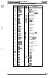
Pin No.
1
2
3
4
5
6
7
8
Pin No.
1
2
3
4
5
6
7
8
!2
Table A-10.
CN6
Pin Assignments
Signal Name
5
VDC
GND1
Pcl
5
VDC
GND1
PC3
24
VDC
SL1
:ON
1/0
—
—
1“
—
—
I
—
o
Description
+5
VDC
Ground
Paper empty
+5
VDC
Ground
Paper exit
+24
VDC
Paper take-up solenoid drive
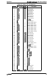
Table A-11. CN7 Pin Assignments
7
Signal Name
GND1
PC2
DC5V
DC24V
GND2
CH1
:ON
CH2:ON
DB:CNT
M3:CNT
1/0
—
I
—
.
—
o
0
0
0
Description
Ground
Paper take-up
+5
VDC
+24
VDC
Ground
Drum charge on
Image transfer on
Developing bias control
M3 control
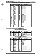
Table A-1 2. CN8
Pin Assignments (Also
CN3
on PWB-E Board)
Pin No.
1
2
3
4
5,6
7,8
9
10
11
Pin No.
1
2
3
4
5
6
7
Signal Name
TdB
TdA
@B
($A
GND1
5
VDC
GND2
24
VDC
H1
:ON
1/0
o
0
0
0
—
—
—
—
o
Description
Ml phase B control
Ml phase A control
Ml phase B clock
Ml phase A clock
Ground
+5
VDC
Ground
+24
VDC
Heater lamp on
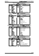
Table A-13.
CN9
Pin Assignments
Signal
Name
I
UO
I
Description
5
VDC
24
VDC
GND2
NC
SL2
S3
PC4
—
—
—
—
o
I
I
+5
VDC
+24
VDC
Ground
Not connected
Lower cassette solenoid on
Lower cassette detected
Lower cassette paper empty
A-12
Rev.
A