
Service manual


EPL-561W/ActionLaser
16tW
Service Manual
General Description
< ‘-’
(’
““
,..
.
.
,
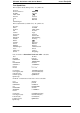
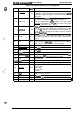
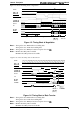
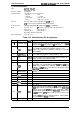
Table 1-8. Parallel Interface Pin Assignment
Pin No.
Signal Name Vo
Description
STROBE
is a strobe pulse used to read data from the host
1
STROBE
IN
computer. The pulse width must be more than 0.5
psec.
Normally it is HIGH, and data is latched at the trailing edge of
this signal.
DATA 1 to 8 are
pa~llel data bits. When the signal is HIGH,
the data bit is 1, and when it
is
LOW, the data bit is O.
2-9
DATA 1-8
IN
The most significant bit
(MSB)
is DATA8. The signal state
must be maintained for 0.5
psec.
on either side of the
STROBE signal active edge.
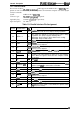
ACKNLG
is an acknowledge pulse with an approximate width
of 1 or 10 wee. This signal goes LOW when the data
10
ACKNLG OUT
reception
is
completed, which indicates that the printer can
accept new data. Timing with the BUSY signal is specified
through
SelecType.
The BUSY signal informs the host computer of the printer
11
BUSY OUT
state. When the signal is HIGH, the printer cannot accept
data.
The PE signal indicates paper empty for the standard tray
12
PE
OUT
selected through
SelecType
or command, or for the optional
paper cassette. Paper empty is indicated by HIGH.
13
SLCT OUT
Use at reverse mode.
14
AUTO-FEED
IN
Not
USd.
15
NC
.
Not
USed.
16
GND
Logic ground level.
17
CHASSIS
GND
-
Connected to the printer chassis. The printer chassis
GND
and the signal
GND
are connected to each other.
18
NC
.
Not connected.
19-30
GND
Ground level for the twisted pair return signal.
31
INIT
IN
The STROBE signal is ignored when this signal is LOW.
This level goes LOW when the printer is:
●
out of paper
32
ERROR
OUT
. paper jam
. in error state
. off line
33
GND
.
Same as for pins 19 to 30.
34
NC
.
Not
USEd
35
+
5
Pulled up to
+5V
through 1.0 Kohm resistance.
36
s
LCT IN
.
Use the reverse mode.
Rev. A
1-11