
Service manual


List of Figures
Figure 2-1. Main Components. . . . . . . . . . . . . . . . . . . . . . . . . . . . . . . . . . . . . . 2-1
Figure2-2. Print Process Diagram . . . . . . . . . . . . . . . . . . . . . . . . . . . . . . . . . . 2-2
Figure2-3.
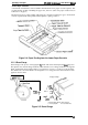
PaperFeedingfrom
the Multi-Purpose Tray. . . . . . . . . . . . . . . . . . 2-3
Figure2-4.
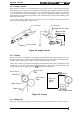
PaperFeedingfrom
the Lower PaperCassette . ..............2-4
Figure2-5. Drum Charge . . . . . . . . . . . . . . . . . . . . . . . . . . . . . . . . . . . . . . . . . 2-4
Figure2-6. LaserExposure. . . . . . . . . . . . . . . . . . . . . . . . . . . . . . . . . . . . . . . . 2-5
Figure2-7. Development . . . . . . . . . . . . . . . . . . . . . . . . . . . . . . . . . . . . . . . . ..2-5
Figure2-8. Image Transfer.. . . . . . . . . . . . . . . . . . . . . . . . . . . . . . . . . . . . . . . 2-6
Figure2-9. Fusing . . . . . . . . . . . . . . . . . . . . . . . . . . . . . . . . . . . . . . . . . . . . . . . 2-6
Figure2-10. Engine Controller Connecting Diagram . . . . . . . . . . . . . . . . . . . . . 2-7
Figure2-11.
Gearand
Roller Positions. . . . . . . . . . . . . . . . . . . . . . . . . . . . . . . 2-8
Figure2-12. P/C Drive Section . . . . . . . . . . . . . . . . . . . . . . . . . . . . . . . . . . . . . 2-8
Figure2-13. Developing Drive Section . . . . . . . . . . . . . . . . . . . . . . . . . . . . . . . 2-8
Figure2-14. Fusing Drive Section. . . . . . . . . . . . . . . . . . . . . . . . . . . . . . . . . . . 2-8
Figure2-15. Feeding Drive Section. . . . . . . . . . . . . . . . . . . . . . . . . . . . . . . . . . 2-8
Figure2-16. Feeding Drive Section (Option). . . . . . . . . . . . . . . . . . . . . . . . . . . 2-8
Figure2-17. Main MotorDriveCircuit . . . . . . . . . . . . . . . . . . . . . . . . . . . . . . . . 2-9
Figure2-18. Paper Take-Up Sensor and Paper Exit Sensor On/OffTiming. . 2-10
Figure2-19. Fuser Control Circuit. . . . . . . . . . . . . . . . . . . . . . . . . . . . . . . . . . 2-10
Figure2-20. Temperature forFuserControl Procedure . . . . . . . . . . . . . . . . . 2-11
Figure2-21. Scanner Motor Control Circuit . . . . . . . . . . . . . . . . . . . . . . . . . . . 2-11
Figure2-22. Scanner Motor Driving Start Timing . . . . . . . . . . . . . . . . . . . . . . 2-11
Figure2-23. Laser Diode Drive Circuit . . . . . . . . . . . . . . . . . . . . . . . . . . . . . . 2-12
Figure2-24. /L DATA Generation Circuit . . . . . . . . . . . . . . . . . . . . . . . . . . . . . 2-12
Figure2-25. Laser Emission PowerAdjustment Timing . . . . . . . . . . . . . . . . . 2-12
Figure2-26. Laser Diode Error Detection . . . . . . . . . . . . . . . . . . . . . . . . . . . . 2-13
Figure2-27. High-Voltage Supply Block Diagram . . . . . . . . . . . . . . . . . . . . . . 2-13
Figure2-28. Print Process. . . . . . . . . . . . . . . . . . . .
...........;..
. . . . . . 2-14
Figure2-29. PowerOnSequence. . . . . . . . . . . . . . . . . . . . . . . . . . . . . . . . . . 2-14
Figure 2-30. Print Sequence (Start). . . . . . . . . . . . . . . . . . . . . . . . . . . . .....2-14
Figure2-31. Print Sequence (End) . . . . . . . . . . . . . . . . . . . . . . . . . . . . . . . . . 2-15
Figure2-32. Fan Motor Speed Control Timing . . . . . . . . . . . . . . . . . . . . . . . . 2-15
Figure2-33. Fan Motor Malfunction Search Timing . . . . . . . . . . . . . . . . . . . . 2-15
Figure2-34. Power Supply Circuit Block Diagram. . . . . . . . . . . . . . . . . . . . . . 2-15
Figure2-35. Video Controller Section . . . . . . . . . . . . . . . . . . . . . . . . . . . . . . . 2-16
Figure2-36. C125MAlN Board Block Diagram. . . . . . . . . . . . . . . . . . . . . . . . 2-16
Figure2-37. Data Flow Diagram . . . . . . . . . . . . . . . . . . . . . . . . . . . . . . . . . . . 2-18
Figure2-38. Reset Circuit . . . . . . . . . . . . . . . . . . . . . . . . . . . . . . . . . . . . . . . . 2-19
Figure2-39. BusControl Circuit . . . . . . . . . . . . . . . . . . . . . . . . . . . . . . . . . . . 2-19
Figure2-40. DRAM Management . . . . . . . . . . . . . . . . . . . . . . . . . . . . . . . . . . 2-20
Figure2-41. Parallel Interface Circuit . . . . . . . . . . . . . . . . . . . . . . . . . . . . . . . 2-21
Figure2-42. RS-232CCircuit . . . . . . . . . . . . . . . . . . . . . . . . . . . . . . . . . . . . . 2-21
Figure2-43.
RS-422Circuit. . .
.
. . . . . . . . . . . . . . . . . . . . . . . . . . . . . . . . . . . 2-22
Figure2-44. LocalTalkCircuit. . . . . . . . . . . . . . . . . . . . . . . . . . . . . . . . . . . . . 2-22
List of Tables
Table2-1. Gearsand Rollers . . . . . . . . . . . . . . . . . . . . . . . . . . . . . . . . . . . . . . 2-9
Table2-2. Functions
ofC125MAlN
Board Main Elements. . . . . . . . . . . . . . . 2-17