
Service manual


EPL-5600
/ActionLaaar
16W
Send@
Manual
Opwatfng
Prindp+as
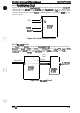
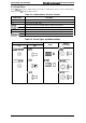
2.2.1.1 Reset Circuit
The
entire system (the CPU and the external devices) can be initialized if the RESET signal (CPU
pin 113) are active simultaneously. This circuit uses an
h451938
IC
to monitor the supply voltage if
a voltage level less than 425 V is detected. The reset time is approximately 128 ma.
+5V
L
f
+
Vcc
OUT
M51938FP
(IC27)
c
+W
L
RSTIN
RSTOUT
E05A92
(IC25)
.
L
~gure 2-38. Reset Circuit
,.
2.2.1.2
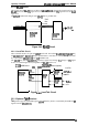
Bus Control Circuit
The
MB86930
CPU outputs the R/W (read/write) signal, AS (address strobe) signal, and the
B131,
BE1, BE2, and
BE3
signals (byte
embles)
to the
ASIC
E05A91.
The
ASIC
E05A91
uses these signals
to generate the RD (read strobe) signal, WR (write strobe) signal, and READY signal.
CPU
MB86930
(ICI)
Rlw—
‘1
As
BEO-3
READY
E05A91
(IC9)
Address Data
~
M
Bus Bus
Figure 2-39. Bus Control Circuit
Rev.
A
2-19