
Service manual


List of Figures
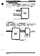
Figure 3-1. Removing the Interface Cover . . . . . . . . . . . . . . . . . . . . . . . . . . . . 3-4
Figure 3-2. Removing the 3 Screws . . . . . . . . . . . . . . . . . . . . . . . . . . . . . . . . . 3-4
Figure 3-3. Pulling the Tab . . . . . . . . . . . . . . . . . . . . . . . . . . . . . . . . . . . . . . . . 3-4
Figure 3-4. Removing the Video Controller Board. . . . . . . . . . . . . . . . . . . . . .. 3-4
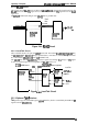
Figure 3-5. Removing the
2Screws
. . . . . . . . . . . . . . . . . . . . . ............3-5
Figure 3-6. Removing the LocalTalk Module. . . . . . . . . . . . . . . . . . . . . .. ....3-5
Figure 3-7. Removing the Control Panel. . . . . . . . . . . . . . . . . . . . . . ........3-5
Figure 3-8. Removing the Housing . . . . . . . . . . . . . . . . . . . . . .............3-6
Figure 3-9. Removing the Rear Frame . . . . . . . . . . . . . . . . . . . . . . . . . . . . . . . 3-7
Figure 3-10. Removing the Engine Controller Board (PWB-A) . ............3-8
Figure 3-11. Removing the Power Supply Unit. . . . . . . . . . . . . . . . . . . . . .. ..3-9
Figure 3-12. Removing the Interlock Switch . . . . . . . . . . . . . . . . . . . . . ......3-9
Figure 3-13. Removing the Optical Unit . . . . . . . . . . . . . . . . . . . . . . . . . . . . . 3-10
Figure 3-14. Removing the Paper Empty Sensor . . . . . . . . . . . . . . . . . . . . . . 3-11
Figure 3-15. Removing the High-Voltage Supply Board . . . . . . . . . . . . . . . . . 3-12
Figure 3-16. Removing the Main Motor. . . . . . . . . . . . . . . . . . . . . . . . . . . . . . 3-12
Figure 3-17. Removing the Fan Motor. . . . . . . . . . . . . . . . . . . . . . . . . . . . . . . 3-13
Figure 3-18. Removing the Fusing Unit. . . . . . . . . . . . . . . . . . . . . . . . . . . . . . 3-13
Figure 3-19. Disassembling the Fusing Unit - 1. . . . . . . . . . . . . . . . . . . .....3-14
Figure 3-20. Disassembling the Fusing Unit -2. . . . . . . . . . . . . . . . . . . . . . . . 3-14
Figure 3-21. Removing the Image Transfer Assembly . . . . . . . . . . . . . . . . . . 3-15
Figure 3-22. Removing the Image Transfer Roller . . . . . . . . . . . . . . . . . . . . . 3-15
Figure 3-23. Removing the Paper Take-Up Assembly . . . . . . . . . . . . . . . . . . 3-16
Figure 3-24. Removing the Paper Take-Up Roller . . . . . . . . . . . . . . . . . . . . .3-17
List of Tables
Table 3-1. Tools . . . . . . . . . . . . . . . . . . . . . . . . . . . . . . . . . . . . . . . . . .......3-1
Table 3-2. Abbreviations Used for Screws . . . . . . . . . . . . . . . . . . . . . . . . . . . . 3-2
Table 3-3. Screw Types and Abbreviations. . . . . . . . . . . . . . . . . . . . . , . . . . . . 3-2
Table 3-4. Checks after Repair. . . . . . . . . . . . . . . . . . . . . . . . . . . . . . . . . . . . . 3-3