
Service manual


EPL-5600
IActionl.aser
16tM
Service
Manuai
DisassembiyandAssembiy
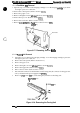
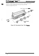
3.2.3.8
Fan Motor
(Q
Removal
1. Open the top cover. Remove the imaging cartridge. Cover the imaging
mrtridge
to protect it
from light or place it in a dark
area.
2. Remove the control panel. (Refer to Section
3.2.l.3.)
3. Remove the paper cover.
4. Remove therightcoverand
Ieftcover.
(Refer to Section
3.2.2.l.)
5. Remove the top cover. (Refer’ to Section
3.2.2.l.)
6. Remove the rear frame. (Refer to Section 3.2.2.2.)
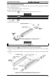
7. Remove 2CCB
SCreWS
(M3
x8),
and
remove the fan motor
(M3).
CCB
(M3
X 8)
Rear Frame
Figure
3-17. Removing the
-
Fan
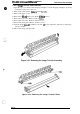
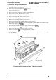
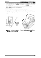
3.2.3.9
Fuaing
Unit Removal
1.
2.
3.
4.
5.
6.
7.
8.
Open the top cover. Remove the imaging cartridge. Cover the imaging cartridge to protect it
from light or place it in a dark area.
Remove the control panel. (Refer to Section 3.2.1.3.)
Remove the paper cover.
Remove the right cover and
Ieftcover.
(Refer to Section
3.2.2.l.)
Remove the upper unit. (Refer to Section
3.2.2.l.)
Remove the rear frame. (Refer to Section 3.2.2.2.)
Disconnect the connector for the thermistor in the fusing unit, the connector for the paper exit
sensor, and CN4 on the power supply board
(PWB-E).
Remove 2 CP(0) screws
(M3
x 6) on the fusing unit, and remove the fusing unit.
~
CP(0)
(M3
X 6)
\
)
(M3
X 6)
Figure 3-18. Removing the Fusing Unit
Rev.
A
3-13