
Service manual


3.2.14 Drive Unit Removal
1. Remove the outer covers. (Refer to Section 3.2.1.)
2. Remove the Fusing Unit. (Refer to Section 3.2.2.)
3. Remove the C207 MAIN Board. (Refer to Section 3.2.4.)
4. Remove the Rear Panel. (Refer to Section 3.2.5.)
5. Remove the Transfer Unit. (Refer to Section 3.2.6.)
6. Remove the High Voltage Supply Board.(Refer to Section 3.2.7.)
7. Remove the Printhead Unit (Refer to Section 3.2.8.)
8. Remove the Paper Empty Sensor Assembly (Refer to Section 3.2.9.)
9. Remove the Paper Takeup Roller Unit. (Refer to Section 3.2.11.)
10. Remove the Registration Roller Assembly. (Refer to Section 3.2.12.)
11. Remove the PWB-A Board. (Refer to Section 3.2.13.)
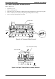
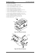
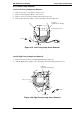
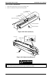
12. Remove 5 CCS screws (3X6) securing the Drive Unit.
13. Remove the Drive Unit.
Drive Unit
Front Side
Figure 3-24. Drive Unit Location
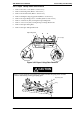
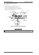
Drive Unit
CCS SCrw (3X6)
PWB-E Board
Front Side
Right Side
Figure 3-25. Drive Unit Removal
EPL-N2000 Service Manual Disassembly and Assembly
Rev. A 3-25