
Service manual

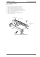


3.2.23 Interlock Switch Removal
1. Remove the main motor. (Refer to Section 3.2.22.)
2. Remove the E ring for the right frame.
3. Remove 10 CCB screws (3X8) securing the right frame.
4. Remove the right frame.
5. Remove 2 CB(S-P1) screws securing the interlock switch, along with the bracket.
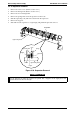
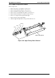
Interlock Switch
CB(S-P1) Screw
Figure 3-40. Interlock Switch Removal (2)
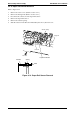
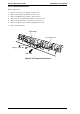
Drive Unit (outside)
Right Frame
CCB Screw (3X8)
E-ring
CB(S-P1) screw
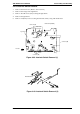
Refer to the
figure below.
CCB Screw (3X8)
CCB Screw (3X8)
Front Side
Figure 3-39. Interlock Switch Removal (1)
EPL-N2000 Service Manual Disassembly and Assembly
Rev. A 3-37