
Service manual
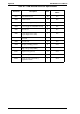

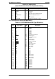
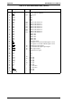
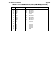

Table A-2. C207 MAIN Board Connector Specifications
Connector Description Pins
Reference
Tables
CN1
Video interface (to PWB-A board)
20 A-3
CN2
IEEE 1284 interface (B connector)
36 1-11 (Chapter 1)
CN3
IEEE 1284 interface (C connector)
36 1-13 (Chapter 1)
CN4
Type-B interface
36 A-15
CN5
I / O bus
40 A-16
CN6
Network interface
8 1-15 (Chapter 1)
CN7
CPU bus
40 A-17
CN9
RAM-SIMM 2
72 A-18
CN10
RAM-SIMM 1
72 A-18
CN11
ROM bus (to C207 PROG board)
80 A-19
CN12
ROM-SIMM
72 A-20
CN14
IC card slot
68 A-22
CN15
Control panel
20 A-23
EPL-N2000 Service Manual Appendix
Rev. A A-3