
Service manual


A.1.1 Engine Controller Board (PWB-A Board)
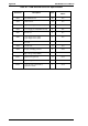
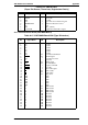
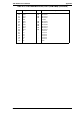
Table A-3 PWB-A, C207 MAIN Board CN1 (Video I/F)
Pin Signal Name I/O Description
1
2
3
4
5
6
7
8
9
10
11
12
13
14
15
16
17
18
19
20
+5V
+5V
RESET
PRRDY
STS
CTBSY
SRCLK
TOD
GND
HSYNC
+5V
—
EPRDY
ETBSY
CMD
PRINT
CPRDY
GND
VIDEO
GND
-
-
O
I
I
O
O
I
-
I
-
I
I
O
O
O
-
O
-
+5 V (Logic power source)
+5 V (Logic power source)
Engine initialize signal
Engine print enable signal
Communication with the engine controller
Command transmit signal
Clock signal
Engine ready signal
Signal ground
Horizontal synchronous signal
+5 V (Logic power source)
Not used
Engine current status signal
Engine status transmit signal
Communication with engine controller
Print start command
Controller current status signal
Signal ground
Video data
Signal ground
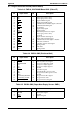
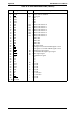
Table A-4 PWB-A CN2 (Printhead Unit)
Pin Signal Name I/O Description
1
2
3
4
5
6
7
8
9
10
11
12
SSCAN
LD.MONITOR
DA2
DA1
GND
LDATA
+5V
+24V
GND
POLYGON_MOTOR
POLYGON_CLOCK
POLYGON_LOCK
I
I
O
O
-
O
-
-
-
O
O
I
Vertical synchronous signal
Laser power detection signal
Laser power adjust signal 1
Laser power adjust signal 2
Ground
Laser drive signal
Laser diode drive power source
Polygon motor drive power source
Ground
Polygon motor drive signal
Polygon motor clock
Polygon motor lock signal
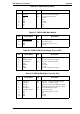
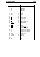
Table A-5 PWB-A CN3 (Paper Near Empty Sensor: PNE1)
Pin Signal Name I/O Description
1
2
3
ANODE
GND
PNE1
-
-
I
Sensor drive signal
Ground
Detection signal
Appendix EPL-N2000 Service Manual
A-4 Rev. A