
Service manual


Disassembly and Assembly
DFX-5000+
Service Manual
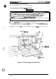
3.2.7 Printer Mechanism Disassembly
This section describes how to disassemble the printer
mechanism.
Before following the steps in this
section, remove the printer mechanism from the printer as described in Section
3.2.6.
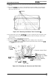
3.2.7.1 Removing the Front/Rear Tractor Select Lever Assembly
1.
2.
3.
Remove the head damper from the left side frame.
Remove the
CPN
(M3
x 6) screw securing the front/rear tractor select lever assembly to the
left side frame.
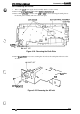
Release the 3 hooks securing the RF motor gear cover to the front/rear tractor select lever
assembly and remove the cover.
RIBBON FEED
GEAR COVER
/
/
‘-+--’?
RIBBON FEED
*
:
//
/
DRIVE GEAR
I
%
~~
‘,.,
/
/
,/0
‘“..
(
k
RIBBON
FEED=
“
,O,&j,
%r,x,~
.’.
(;(
,Jf~:2,,q
, ,-.
MOTOR
‘-
,/,
“:.
‘.”~~>
RIBBON FEED
MOTOR FRAME ,/” ”
=
“’~.’
,.
‘>.
.,
CPN
(M3x6)
“*.<
,.$:;<,
““’”’’:,2:,,,;’’”
,
::
,,
~~•
“’\-.<
..:::
. . .
..+
.
~~~~•
~~
>,
~~•ŒÌ•Ž•ˆ••Œ$¬…• …z••
.:.,:;
Figure 3-31. Removing the Tractor Select Lever
1
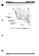
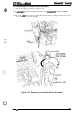
4. On the connector junction board assembly, disconnect the white, 6-pin connector for RF motor
control and the yellow, 2-pin connector for the tractor select sensor.
5. Remove the
CPN
(M3
x 6) screw securing the front/rear tractor select lever assembly to the
left side frame.
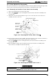
6. Remove the RF motor drive gear from the front/rear tractor select lever assembly. Then
remove the lever assembly from the left side frame.
3
Connector Junction Board
,:
$$j}{f$lj
<
.“1
R/F Change Lever
+
f@~’
[C
-/
,/
‘a
.
‘
\,
Unit
q$$
$<.
;=9~
Connector for
P
‘\
.>
RIBBON FEED MOTOR
\J
, . .
Connector for TRACTOR
.=
j,
SELECT SENSOR
——. .
.
-.
CPN
(M3x5)
Figure 3-32. Removing the Tractor Select Lever 2
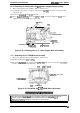
When you install the
frontlrear
tractor select lever assembly, join the tip of the tractor select
lever and the tractor select gear holder correctly. (Refer to Figure 2-12.)
3-24
Rev.
A