
Service manual

DFX-5000+
Service Manual
llsassembty and
Assamb&
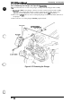
3.2.7.2 Disassembling the Front/Rear Tractor Select Lever Assembly
This
section
describes how to disassemble the front/rear tractor select lever assembly, including
how to remove the RF motor and tractor select sensor.
1.
Remove the front/rear tractor select lever assembly. (Refer to Section 3.2.7.1)
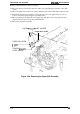
2.
Remove
the
2
CP
(PS)
(M3 x 6) screws securing the RF motor to the front/rear tractor
select
lever assembly and remove the motor.
Discomect
the cable from the black
comector
on the
RF motor.
3. Remove the E ring (#3) securing the front/rear tractor select lever and remove the lever.
Remove the E ring (# 3) securing the tractor select cam and remove the mm.
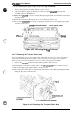
4.
Remove the
CPS
(IW2
x 10)
screw
securing the tractor select sensor and remove the
wnsor.
r.
...,
.’\
,,
,,
%+
c
“/)
T&W&”
SELECT “
/
\
.!?
‘o
L“”
-- . ---- A-,
-A-
/
1
HAG I
UH
StLtb
I
~~
LEVER LOWER
1
!
RIBBON
FEED MOTOR
FRAME
m
~
RIBBON FEED
\
MOTOR
i
‘a
I
‘CP
(PS)
(M3x6)
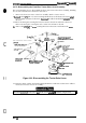
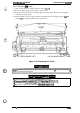
Figure 3-33. Disassembling the Tractor Select Lever
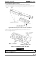
5. Using wire cutters, cut the wire band securing the RF motor and tractor select sensor cables to
the front/rear tractor select lever assembly.
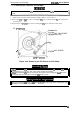
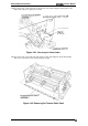
Attach the
fiontlrear
tractor select
leoer
to the tractor sekct
cam
as shown in Figure 3-34.
c)
Rev.
A
3-25