
Service manual

DFX-5000+
SeWica
Manual
Disassembly and Assembly
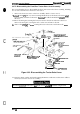
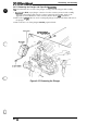
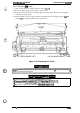
3.2.7.3 Removing Connector Junction Board
Aasembly
and
FPC
Board
Aeaembly
This section describes how to remove the
comector
junction board assembly (also
died
the
relaying board) and
FPC
board assembly.
1.
Remove the left side cover. (Refer to Section 3.2.3.2)
2. Disconnect all the cables from
theconnectorjunction
board assembly. Remove the2CP
(PS)
(M3
x 6) screws securing the connector junction board assembly to the printer mechanism and
then remove the connector junction board assembly.
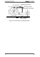
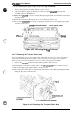
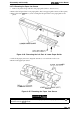
3. Remove the front/rear tractor select lever assembly. (Refer to Section 3.2.7.1)
4.
Disconnect the connector for the CR sensor (encoder) from the
FPCboard
assembly.
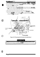
5. Remove the 2
CPN
(M3
x 8) screws securing the
FPC
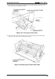
cover and remove the cover.
Then
remove the
CPB
(M3
x 6) screw securing the
FPC
board assembly to the printer mechanism
and remove the
FPC
board assembly.
62
,,
J,-
.,. .
,.
;f
Connector
Board
\\
C-)
I
f
/1”
I
II
I
F
‘
n
\
no
—
\
!lI
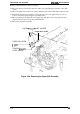
Figure 3-35. Removing the Connector Junction Board
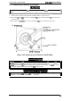
When you connect the cables to the connector junction board assembly, note that the matching
connectors have the same color and number of
p“ns.
(’l%e
Appendix provides the connector pin
assignments for the connector junction board assembly.)
Rev.
A
3-27