
Service manual


G
,p:
-,.
DEX-5000+
Service Manual
Disassembly and Assembly
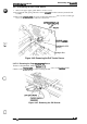
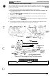
3.2.7.15 Removing the Front Tractor Assembly
This section describes how to remove the front tractor assembly. You need to remove the front
tractor assembly before removing the white, 3-pin, front PE sensor connector from the
mnnector
junction board assembly.
1.
Remove the connector junction board assembly. (Refer to Section 3.2.73)
2. Loosen the hexagonal nuts securing the shaft at the front of the front tractor assembly to the
left and
right side frames.
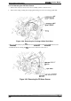
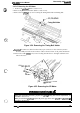
3. After
loosening
thehexagond
nut on the right
side, remove the right tractor wire spring
holder set.
4. To release the tractor wire, remove the CPN (M4
x
8) screw securing the left tractor wire
spring holder set to the left side frame.
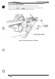
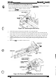
5. Remove the E-ring Securing
thestmftat
the back of the front tractor assembly to the left side
frame.
6. To remove the front tractor assembly, first move it to the left. Remove the right side of the
shaft by pulling it forward, and then remove the left side of the shaft.
—
-
-
,/
.
.
.,
.
,
/
\
‘\\
c)
( .
.+
HQLDER
(R)
TRACTOR
W[
‘L
WIRE SPRING
,/
~..
L.
\
ni.
3N\i
‘(”
I
.
,’
+f
b
:-
“-L
Hexagonal Screw
/
.
.
E ring
(6)
-’ji5+RiF2Y~::~::i’::r
.nan.o,.er=,
-~/&~TRAcToRAssEMBLy
,FRoN’’asher
E
ring
(6)
1.
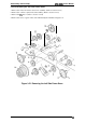
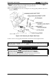
Figure 3-52. Removing the Front Tractor Assembly
1
When you install
the
front tractor assembly,
peq%rm
the tractor wire spring adjustment, as
described in Section 4.1.3.
b
Rev.
A