
Service manual


Disassembly and Assembly
DFX-5000+
Service Manual
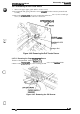
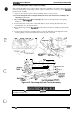
7.
Remove
the carriage damper from therightside frame, and remove the
3
CBS (0) (M4x 8)
screws securing the carnage motor holder to the right side frame.
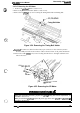
8.
Remove the right guide shaft holder lever.
9.
Remove the 2
CP
(PS)
(M4
x 6) screws
securing the rear carriage guide parallelism adjust lever
and remove the lever.
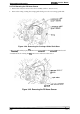
Figure 3-59. Removing the Right Side Frame
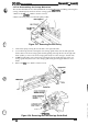
10. Remove the rear carriage guide shaft with the carriage base from the right side frame.
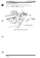
When you install the
front
carriage guide
shafl,
tighten the screws while pushing the shaft
toward the platen.
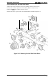
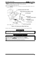
When you assemble the
cam”age
mechanism, perform the following adjustments:
Q
Carriage timing belt tension adjustment (described in Section
4.1.2)
D
Carriage guide shaft
parallelistn
adjustment (described in Section 4.1.5)
D
Platen gap motor value (platen gap) adjustment (described in Section 4.1.7)
Q
Bidirectional printing adjustment (described in Section 4.1.8)
3-44
Rev.
A