
Service manual


CHAPTER 5 Troubleshooting
Table of Contents
5.1 TROUBLESHOOTING INFORMATION
5-1
5.1.1 Error Messages.. . . . . . . . . . . . . . . . . . . . . . . . . . . . . . . . . . . . . . . . . . .
5-1
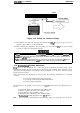
5.1.2 Bypassing the lnterlockSwitch and Cover Sensor . . . . . . . . . . . . . . . . . 5-2
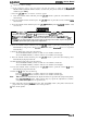
5.1.3 Coil Resistance.. . . . . . . . . . . . . . . . . . . . . . . . . . . . . . . . . . . . . . . . . . . 5-3
5.2 REPAIR BY UNIT REPLACEMENT
5-4
5.3 REPAIR OF THE POWER SUPPLY CIRCUIT
5-13
5.4 REPAIR OF THE
C117
MAIN BOARD ASSEMBLY
5-17
5.5 PRINTER MECHANISM
5-24
List of Figures
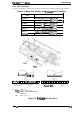
Figure 5-1. Bypassing the Interlock Switch . . . . . . . . . . . . . . . . . . . . . . . . . . . . 5-2
Figure 5-2. Bypassing the Cover Open Sensor. . . . . . . . . . . . . . . . . . . . . . . . . 5-2
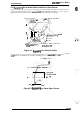
Figure 5-3.
Printhead Coil Resistance. . . . . . . . . . . . . . . . . . . . . . . . . . . . . . . . 5-3
List of Tables
Table 5-1. Error Codes . . . . . . . . . . . . . . . . . . . . . . . . . . . . . . . . . . . . . . . . . . .
5-1
Table 5-2. Motor, Fan, Plunger, and
Printhead
Coil Resistance . . . . . . . . . . . . 5-3
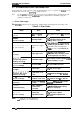
Table 5-3. Symptoms and Reference Pages. . . . . . . . . . . . . . . . . . . . . . . . . . . 5-4
Table 5-4. Cl 17
PSB/PSE Board Assembly Main Parts List. . . . . . . . . . . . . . 5-13
Table 5-5.
C117 PSBIPSE Board Assembly Component Repair. . . . . . . . . . . 5-13
Table 5-6.
C117 MAIN Board Assembly Component Repair. . . . . . . . . . . . . . 5-17
Table 5-7. Printer Mechanism Repair . . . . . . . . . . . . . . . . . . . . . . . . . . . . . . . 5-24