
Service manual


Appendix
DEHOtXl+
Service Manual
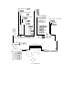
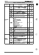
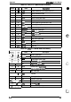
Table A-5. CN4, C117 MAIN Board Assembly
Pin No.
UO
Name
Oesoription
1-6
I
+5V
Power source for
Type B optional interface
7
0
TXD
Serial transmission data
8
0
READY
Ready to receive data
9
I
RXD
Serial receiving data input
10
.
NC
Not connected
11
0
m
Reset signal for Type B interface card
12
0
INH
Inhibit signal output
13
I
CMREQ
Command request signal input
14
I
WRRDY
Wriie
ready signal input
15
I
RDREQ Read
rquest
signal input
16
0
m
Wriie
signal input
17
0
m
Read signal input
18
0
@
Chip select signal input
I
,
19-24
-
GND
Ground
25-28
0
A3-AO Address output
29-36
1/0
D7-DO
Data bus
a=
1
I
2-9
1/0
10
0
11
0
12
0
I
13
0
I
14
I
I
15,34
-
t
16,1&-30,
-
17
-
31
I
32/0
18,35
]
I
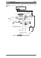
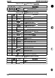
Table A-6.
CN5,
Cl 17 MAIN Board Assembly
Name
Description
STRBX
I
Strobe signal input
DATA1
-8
I
Data input/output
ACK
Acknowledge signal output
I
BUSY
I
Busy Signal
OUtpUt
I
PE
I
Pa~rendsi!malo
utpuf
SLCT
I
Printer select
si9naloutP@
AFXT
I
Atiolinefeedshnal
input
NC
I
Not connected
GND
Ground
FG
I
Frame ground
INIT
Initialize signal input
ERR
Error signal output
+5V
+5 VDC
@
UP
SLIN
Printer select signal input
6-’:.,
b
,,
A-4
Rev.
A