
Service manual


Product Description
LKMO#+
Serukw
Mwd
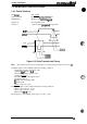
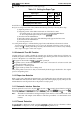
1.3 INTERFACE SPECIFICATIONS
1.3.1 Parallel Interface
Data
forrmt:
8-bit parallel
Synchronization:
By STROBE
Pllk
Sy’dWXWa
“ tion
Handshaking:
By BUSY and
ACKNLG
SigdS
Signal level:
TT’compatible level
Connector:
%-pm 57-30360
(Amphenol)
or equivalent
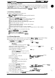
ACKNLG
DATA
&
L
0.5uS(Min.)
O.SuS(Min.)
0.5uS(Min.)
Figure 1-22. Data Transmission Timing
Note:
The transition time (the rise and fall time) of each input signal must be less than 0.2
ILS.
The BUSY signal is active (HIGH) under the following conditions:
- During data reception (See Figure 1-22.)
- When the
~t
buffer is
full
- When the INIT’ input signal is active
- During initialization
- When the ERROR or PE signal is active
- During the self-test
-
II-I
paper memory setting mode
-
IrI
pause mode
- When a fatal error occurs
6!’!?
.,
‘,$
‘.
.>..
,:,
The ERROR signal is active (LOW) under the following conditions:
- When a paper out error occurs
- When a paper jam error occurs
- When a fatal
error
occurs
The PE signal is active (HIGH) when a paper out error occurs.
1-14
Rev.
A