
Service manual


DFX-5000+
Sendee
Mama!
O~atfng
Princi@aa
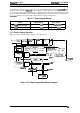
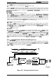
The
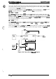
power supply board converts the AC voltage to the DC voltages required to operate the
e
printer. The AC voltage is input to the AC inlet, and is supplied to the
C117
power supply board
assembly via the power switch and fuse.
l’hree
switching regulator circuits convert the AC voltage
to the three DC voltages (+35 V,
+5
V, and +/-12 V) required to operate the printer.
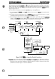
The
power supply board contains two +35
VDC
creation circuits.
(Ike
+35
VDC
line is divided into
two sections.) One +35
VDC
line supplies power to six of the nine
printhead
pins (pins 1,3,5, 7,8,
and 9); the other +35
VDC
line supplies power to three of the nine
printhead
pins (pins 2,4, and 6)
and to the motors.
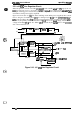
These switching regulator circuits perform voltage control and over-current limiting for each
voltage. They supply or cut the DC voltage based on the
DRERR
(Driver Error) signal from the
C117
MAIN board assembly, and output the
CLIMIT
(Power Down) signal when the printer has
exceeded its duty cycle (the
printhead
temperature is too high).
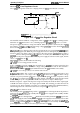
The
Cl17
power supply board assembly includes a cooling
km
that is driven by the +35
VDC.
The
fan lowers the temperature of the circuit components, and is located under the carnage motor so
that it also lowers the carriage motor temperature.
To prevent a surge in the current, the power supply board cannot recover for approximately
thee
minutes after the power is turned off. Therefore, after the printer is turned off, wait three minutes
before you turn it back on.
m
The specifications for the
C117
power supply board assembly depend on the board type (120 V
%i;’
C117
MB
or 220/240 V
C117
PSE).
Before using a different AC power supply, replace the fuse and power cord.
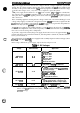
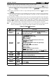
Table
2-2. DC Voltages
Voltage Rated Current
Application
Q
Printhead
drive
Q
CR motor drive
Q
PF motor drive
+35
V
(CN2)
2A
Q
PG
motor
drive
Q
RF motor drive
Q
Plunger drive
Q
Head fan motor drive
+35
V
(CN4)
2A
Cl Fan power for
coding
the CR motor
O
All
Iogio
systems (Cl 17 MAIN board
assembly and Cl 17 PNL
bad
~w
operating voltages)
+5 V
(CN3)
1.0 A
Q
CR motor hold voltage
Cl
~U~W
hold
vda~
Q
i%
motor hold voltage
0
Power for ail the sensors
Cl
Cl
17 MAIN board assembly operating
+12 V
(CN3)
0.1 A
voltage (serial interface conversion and
Type
B optional
interface voltage supply)
-12 V
(CN3)
0.1 A
D
F~
trigger for
printhead
firing
Note:
Before the power supply board outputs +35
VDC,
it outputs +13
VDC
to the
printhead
drivers on the
C117
MAIN board assembly. ‘This procedure is a driver check to prevent
printhead
damage.
c)
.:.
-
,.,
.*
,
,,
Rev. A
2-13