
Service manual


DFX-5000+
Service Manual
operating
Principbe
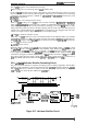
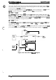
2.2.3 +35
VDC
Line Regulator Circuit
When the printer is turned on and the
C117
MAIN
board assembly
sends
the
WC
signal, the +35
VDC
line rises from +13 V to +35 V. The +35
VDC
line arcuit uses a ringing choke
mnvertor
(RCC)
AC input switching power circuit. This system uses few parts and a small transformer, and is
ok
used when a small power supply is required.
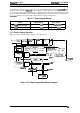
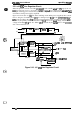
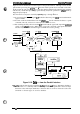
Figure 2-16 shows the +35
VDC
line
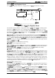
main switching circuit. When power is applied, drive current
flows to the gate of switching FET
(Q101)
via starting resistor
R118.
Diodes
D157,
D156,
D151,
and
D251
on the secondary side of
T1
and T2 prevent current flow in the
secondary side. When
QIOl
is
turned on, the primary side of transformer coil
T2-3
receives an
rnput
voltage, which induces
voltage in windings
W-4
and ‘12-3. When
Q101
is turned off, the
currmt
flows to the
wamdary
side of the transformer coil.
o
Filter
Clrcuk
Surge-cul
R9ctifbr “
smoothing
Circuit
arcuit
C&wit
o
H
H
H
h
I
(“
,,p:..
,
“:.>..
a
T
al%
Main
sWching
Smmthing
--0
+35
VDc
-
OREFIRS@d
Circuif
(1)
Clrcuif
a
a
O
GP
Over Current
Protection
+/-13
v
Creatial
(ZD151,181
/
ZD1S2-1S5)
0-
WC
Sigrui
Circuit (IC101,2O1)
Main switching
Smcdhing
0--0
Cimllit
+35
VDc
a
o
GP
Transformer
+35
WC
Drop Monitor
O
~
CI.MT
signal
ckcuii
(NJM2903)
+35V
O/er
Volmga
Prokxiorl
Ck4it
(91s3,0353)
Figure 2-16. +35
VDC
Line Regulator Circuit
c’
. .
.
.
.
{
. . .
c
)
Rev.
A
2-15