
Service manual


Operating Principles
DEX4000+
Service
Manual
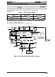
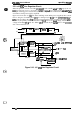
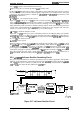
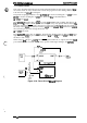
5. The
print data is stored in the line buffer in units of one line of data.
6.
The CPU reads the print data stored in the line buffer byte by byte, accesses the
CG
(Character
Generator), and expands the data in the image buffer (in the case of download characters, in
the download
CG).
A row of expanded data is output to the
printhead
control circuit as head
data.
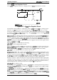
7. When data is expanded to an italic or super/subscript character, the CPU uses
IC7
to expand it
via
MMIO.
8. The CPU controls the CR motor by calculating the control data for each line from the print data
in the line buffer. When a paper feed command is sent after one line is printed, the CPU
executes paper feeding.
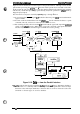
For NLQ characters, printing one line consists of two passes; the printer performs steps 6 through 8
twice. When the CPU expands the data from the CG in the image buffer, it uses the 24-bit shift
register in
IC7.
The CPU is always ready to fetch data so printing can be viewed as an
interrupt-to-fetch operation.
Whenever the input data buffer is not full between printing
operations, data is fetched. Table 2-3 describes the functions of the main printer components.
Note:
The data flow from the serial interface is the same as the data flow from the parallel
interface, described above, except the signal names and data access method differ.
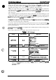
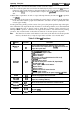
Table 2-3. Main
IC
Functions
IC
Name
Location
Functions
TMP96C141
Receives data from the host computer via the gate array,
(CPU)
Icl
loads the data to the input buffer in
PS-RAM,
and converts the
image data to print data.
Th&main
E05A87
features are:
Q
CS
(Chip Select) signal creation
D
Address decoding
Q
Address latching
Cl
Clock pulse creation (divided from the CPU clock)
Q
Printhead
driver control
D
CR motor driver control
E05A87
IC7
LI
CR and PG motor pulse encoder l/O (input/output)
Q
Encoder pulse
1/0
Q
Phase signal creation for the motors
Q
i/O port control
Q
Interface control
Q
Abnormal CR and PF motor detection
Q
RESET signal creation
Q
Control signal creation for the power supply
board
PROM
PROM
IC4
Contains the program that runs the CPU.
PS-RAM
IC3
Holds the CPU working area and buffers
(input, line, and image buffers).
SLA7026
ICI
1
Drives the RF motor and controls the constant current.
SDC03 QM2
Drives the PG motor.
NJM2903
Iclo
Detects the current in the CR motor driver and feeds it back to
the gate
away.
SLA5007
QM1
Drives the CR motor.
2-20
Rev.
A