
Service manual


Disassembly and Assembly
DFX-5000+
Service Manual
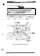
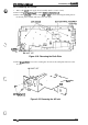
4.
While supporting the top cover to protect it from scratches, tilt back the printer and lay it on
its back.
5. Remove the
8
CPB
(M4
x 16) screws securing the bottom panel assembly. Slowly return the
printer to its upright position before you remove the screws for the bottom panel assembly.
Then remove the rear cover.
CPB
(M4x16)
Figure 3-19. Removing the Bottom Panel Assembly
1
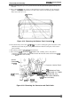
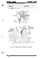
6.
From the left side, remove the
2
CPB
(0)
(M4
x 8) screws securing the green and yellow earth
cable between the bottom plate of the printer mechanism and the earth plate on the bottom
panel assembly.
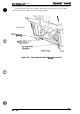
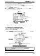
7. Disconnect connectors
CN1O,
CN6,
CN7,
and CN8.
8. Since comector
CN9
is fixed to the
C117
MAIN board assembly, remove the junction
connector (not labeled with a CN number) between the interlock switch and connector
CN9
on the
C117
MAIN board assembly.
Junction
Connector
-
(for
CN9)
CFJ8
(Control
Panel)
Connector Junction Board
CN6
(Mechanism Drive)
BOARD ASSY.,C117 MAIN
CN1O
(DETECTOR, CR)
~CN7
(CASE OPEN SENSOR)
CN9
(Inter Lock Switch)
CPB
(0)
(M4x8)
(LEFT Side)
Figure 3-20. Removing the Connector and Earth Cable
3-16
Rev.
A