EPSON TERMINAL PRINTER EPSON/Stylus Color 200 EPSON/Stylus 200 SERVICE MANUAL EPSON Rev.
NOTICE All rights reserved. Reproduction of any part of this manual in any form whatsoever without SEIKO EPSON’s express written permission is forbidden. The contents of this manual are subjects to change without notice. All efforts have been made to ensure the accuracy of the contents of this manual. However, should any errors be detected, SEIKO EPSON would greatly appreciate being informed of them.
PRECAUTIONS Precautionary notations throughout the text are categorized relative to 1) personal jnjuury and 2) damage to equipment. DANGER Signals a precaution which, if ignored, could result in serious or fatal personal injury. Great caution should be exercised in performing procedures preceded by DANGER Headings. WARNING Signals a precaution which, if ignored, could result in damage to equipment.
PREFACE This manual describes functions, theory of electrical and mechanical operations, maintenance, and repair of Epson Stylus Color 200 /Epson Stylus 200. The instructions and procedures included herein are intended for the experience repair technician, and attention should be given to the precautions on the preceding page. The chapters are organized as follows: CHAPTER 1. PRODUCT DESCRIPTION Provides a general product overview, lists specifications, and illustrates the main components of the printer.
REVISION SHEET Revision Issue Date Contents Rev.
TABLE OF CONTENTS CHAPTER 1. CHAPTER 2. CHAPTER 3 CHAPTER 4. CHAPTER 5. CHAPTER 6.
Chapter 1 Product Description Table of Contents 1.1 OVERVIEW 1-1 1.2 SPECIFICATIONS 1.2.1 Printing Specifications . . . . . . . . . . . . . . . . . . . . . . . . . . . . . . . . . . . . . . 1.2.2 Paper Handling Specifications . . . . . . . . . . . . . . . . . . . . . . . . . . . . . . . . 1.2.3 Paper Specifications . . . . . . . . . . . . . . . . . . . . . . . . . . . . . . . . . . . . . . . . 1.2.4 Ink Cartridge Specifications . . . . . . . . . . . . . . . . . . . . . . . . . . . . . . . . . . 1.2.
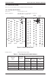
List of Figures Figure 1-1. Exterior View of EPSON Stylus Color 200 . . . . . . . . . . . . . . . . . . 1-1 Figure 1-2. Nozzle Configuration . . . . . . . . . . . . . . . . . . . . . . . . . . . . . . . . . . . 1-2 Figure 1-3. Printable Area. . . . . . . . . . . . . . . . . . . . . . . . . . . . . . . . . . . . . . . . . 1-4 Figure 1-4. Paper Select Lever . . . . . . . . . . . . . . . . . . . . . . . . . . . . . . . . . . . . . 1-5 Figure 1-5. Temperature / Humidity of Range . . . . . . . . . . . . . . . .
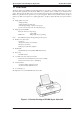
Epson Stylus Color 200 /Epson Stylus 200 Product Description 1.1 FEATURES The Epson Stylus Color 200/Epson Stylus 200 printer are color ink jet dot matrix printers that come with a 64-nozzle black printhead and a 60-nozzle CMY color printhead, either of which can be installed in the printer. The Epson Stylus 200 version comes standard with only the 64-nozzle black printhead; however, the CMY color printhead can be purchased as an optional upgrade.
Product Description Epson Stylus Color 200 /Epson Stylus 200 1.2 SPECIFICATIONS This section provides statistics and other detailed information for the printer. 1.2.
Epson Stylus Color 200 /Epson Stylus 200 Character tables: Product Description Legal and 14 international sets Table 1-2. Character Tables Bitmap Fonts Character Tables Standard NLSP EPSON Roman EPSON Roman EPSON Sans Serif EPSON Sans EPSON Courier Serif Italic PC437 (U.S./Standard Europe) PC850 (Multilingual) PC860 (Portuguese) PC861 (Icelandic) PC863 (Canadian-French) PC865 (Nordic) Abicomp BRASCII Italic PC437 (U.S.
Product Description Epson Stylus Color 200 /Epson Stylus 200 1.2.2 Paper Handling Specifications Feeding method: Friction feed paper is fed from the built-in auto sheet feeder (ASF). Line spacing: 1/6 inch feed or programmable in 1/360 inch minimum increments. Paper path: Cut sheets are fed from the built-in auto sheet feeder (ASF). Top in and front out. Feeding speed: 102 msec. (at 1/6-inch feed pitch). 1.2.3 Paper Specifications Table 1-3.
Epson Stylus Color 200 /Epson Stylus 200 Product Description The adjust lever on the upper case must be set to the proper position for the paper thickness, as shown in Table 1-4. Table 1-4. Adjust Lever Settings Paper Lever Position Paper Thickness Cut Sheets Front (0 position) 0 mm Envelops Rear (+position) 0.62 mm Also the paper select lever on the upper case must be set to the proper position for the paper varieties shown in Table 1-5. Table 1-5.
Product Description Epson Stylus Color 200 /Epson Stylus 200 1.2.4 Ink Cartridge Specifications Table 1-6. Black I/C Specifications Item Specifications Type Exclusive cartridge Color and Weight Approximately 54 g (internal ink weight is 36 g ± 0.
Epson Stylus Color 200 /Epson Stylus 200 Product Description 1.2.5 Electrical Specifications Table 1-8. Rated Electrical Ranges Specification 120 V Version 220 - 240 V Version Rated voltage 120 VAC Input voltage range 103.5 ∼ 132 V 198 ∼ 264 V Rated frequency range 50 ∼ 60 Hz 50 ∼ 60 Hz Input frequency range 49.5 ∼ 60.5 Hz Rated current 0.5 A Power consumption Approx. 15 W Approx.
Product Description Epson Stylus Color 200 /Epson Stylus 200 1.2.7 Reliability Total print volume: 25,000 pages (A4, letter) MTBF: 4000 POH (Duty 7%) MCBF: 1 million pass ( except print head) Printhead life: 1000 million dots/nozzle (color and monochrome) 1.2.8 Safety Approvals Safety standards: 120 V version: 220-240 V version: Radio frequency interference (RFI): 120 V version: 220-240 V version: UL1950 with D3, CSA C22.
Epson Stylus Color 200 /Epson Stylus 200 Product Description 1.3 INTERFACE SPECIFICATIONS The EPSON Stylus Color 200/EPSON Stylus 200 is standard-equipped with an 8-bit parallel and serial interface. 1.3.
Product Description Epson Stylus Color 200 /Epson Stylus 200 Table 1-10 and 1-11 shows the connector pin assignments and signal functions of the 8-bit parallel interface. Table 1-10. Signal and Connector Pin Assignments for Parallel Interface Pin No. * Signal Name I/O* Description 1 -STROBE I Strobe pulse. Input data is latched at falling edge of the signal. 2-9 DATA 1-8 I Parallel input data to the printer.
Epson Stylus Color 200 /Epson Stylus 200 Product Description 1.3.
Product Description Epson Stylus Color 200 /Epson Stylus 200 1.4 OPERATIONS This section describes the basic operations of the printer. 1.4.1 Control Panel The control panel for this printer has 2 non-lock-type push buttons, and 3 LED indicators for easy operation of the various printer functions. Power Inkout Paperout Cleaning Load / Eject But to n L ig h t Figure1-7. Control Panel Appearance 1.4.
Epson Stylus Color 200 /Epson Stylus 200 Product Description Table 1-13.
Product Description Epson Stylus Color 200 /Epson Stylus 200 1.4.3 Default Settings The printer can save some printer setting parameters that define its functions at initialization. You can change these parameters using the printer’s default setting mode. 1.4.3.1 Default Setting Items You can use default setting mode to change settings listed in the table below. Activate default-setting mode by holding down the Load/Eject and Cleaning buttons while turning on the printer. Table 1-16.
Epson Stylus Color 200 /Epson Stylus 200 Product Description Table 1-17. Default Setting Items (Continued) Item Contents Auto line feed Off On Loading position 8.5 mm 3 mm Thick paper Envelopes Index card (portrait) Note: The underlined value is the factory setting. 1.4.3.2 Changing the Default Settings User is requested to operate 2 buttons watching 3 lights on the control panel.
Product Description Epson Stylus Color 200 /Epson Stylus 200 1.4.4 Error Conditions The printer can detect various errors and indicate them with LEDs. Refer to Table 1-14. 1.4.5 Printer Initialization There are three initialization methods: power-on initialization, software initialization and operator initialization. 1.4.5.1 Power-On Initialization This initialization of this level is activated by power-on or cold-reset command(remote RS command).
Epson Stylus Color 200 /Epson Stylus 200 Product Description 1.5 MAIN COMPONENTS The main components of the Stylus Color IIs are: ❏ ❏ ❏ ❏ ❏ Printer mechanism (M-4C11) Main control board (C199 MAIN Board) Power supply unit (C160 PSB/PSE Board) Control panel board (C160 I/F Board) Housing 1.5.1 Main Control Board (C199 MAIN Board) The main control board (C199 MAIN Board) consists of an M37721S2BP 16-bit CPU. The E05B32 gate array operates with 25MHz clock speed and controls various memories.
Product Description Epson Stylus Color 200 /Epson Stylus 200 1.5..2 Power Supply Board (C160 PSB/PSE Board) The power supply board (C160 PSB/PSE Board) consists of an RCC switching regulator circuit. This board does not have a power switch connected to the secondary circuit like the Stylus Color series. Thus, if the printer is turned off, it cannot continue to operate in order to perform the head capping operation.
Epson Stylus Color 200 /Epson Stylus 200 Product Description 1.5.4 Printer Mechanism (M-4C11) The M-4C10 printer mechanism is equipped with a replaceable 64-nozzle black printhead and 60-nozzle color (CMY) printhead, and it can print at a high resolution (720 dpi) using the special coated paper. Figure 1-11.M-4C11 Printer Mechanism 1.5.5 Housing The Epson Stylus Color 200/Epson Stylus 200 housing consists of the printer cover, upper case, and lower case.
Chapter 2 Operating Principles Table of Contents 2.1 OVERVIEW 2-1 2.1.1 C199 Main Board . . . . . . . . . . . . . . . . . . . . . . . . . . . . . . . . . . . . . . . . . . . 2-1 2.1.1.1 Carriage Motor Driver Circuit . . . . . . . . . . . . . . . . . . . . . . . . . . . 2-2 List of Figures Figure 2-1. C199 Main Board . . . . . . . . . . . . . . . . . . . . . . . . . . . . . . . . . . . . . . . 2-1 Figure 2-2. Carriage Motor Drive Circuit Block Diagram . . . . . . . . . . . . . . . .
EPSON Stylus COLOR 200 / EPSON Stylus 200 Operating Principles 2.1 OVERVIEW Since the printer mechanism of the EPSON Stylus COLOR 200 is the same as for the EPSON Stylus COLOR IIs, this section only describes the differences in electrical circuitry. 2.1.1 C199 MAIN BOARD The main control board for the EPSON Stylus COLOR 200 is the C199 MAIN board.
Operating Principles EPSON Stylus COLOR 200 / EPSON Stylus 200 2.1.1.1 Carriage Motor Driver Circuit Carriage motor driver IC UDN2917EB (IC8) outputs a constant current to drive the carriage motor. CPU M3772152BFP (IC2) determines the motor phase and speed, and then sends a signal to the UDN2917EB carriage motor driver IC (IC8) via a 4-bit signal transmission line. The carriage motor is controlled by a 2W1-2 phase drive method. The figure below shows the carriage motor driver circuit block.
EPSON Stylus COLOR 200 / EPSON Stylus 200 Operating Principles In the Table 2-1, if the control sequence is executed in incremental order, the carriage motor rotates clockwise (CW). (The CR moves from 1st column to 80th column.) Signals output from ports P105, P106, and P107 of the CPU determine the reference trip current level used by the motor driver IC for drive current control. Table 2-2 lists the connection of the output signals and the reference trip current levels. Table 2-2.
Chapter 3 Disassembly and Assembly Table of Contents 3.1 OVERVIEW 3-1 3.1.1 Precautions for Disassembling the Printer . . . . . . . . . . . . . . . . . . . . . . 3-1 3.2 DISASSEMBLY AND ASSEMBLY 3-1 3.2.1 Upper Case Removal . . . . . . . . . . . . . . . . . . . . . . . . . . . . . . . . . . . . . . . . 3-2 3.2.2 C199 Main Board Removal . . . . . . . . . . . . . . . . . . . . . . . . . . . . . . . . . . . . 3-3 3.2.3 C160 I/F Board Removal . . . . . . . . . . . . . . . . . . . . . . . . . . . . . . . . . . .
LIST OF FIGURES Figure 3-1. Upper Case Removal . . . . . . . . . . . . . . . . . . . . . . . . . . . . . . . . . . . 3-2 Figure 3-2. C199 Main Board Removal . . . . . . . . . . . . . . . . . . . . . . . . . . . . . . 3-3 Figure 3-3. ASF Sensor Removal. . . . . . . . . . . . . . . . . . . . . . . . . . . . . . . . . . . 3-3 Figure 3-4. Board Frame and Metal Stay Removal. . . . . . . . . . . . . . . . . . . . . 3-4 Figure 3-5. C160 I/F Board Removal . . . . . . . . . . . . . . . . . . . . . . . . . . . . . .
EPSON Stylus Color 200 / EPSON Stylus 200 Disassembly and Assembly 3.1 OVERVIEW This section describes procedures for disassembling the main components of the printer. Unless otherwise specified, disassembled units or components can be reassembled by reversing the disassembly procedure. Therefore, no assembly procedures are included. Precautions for any disassembly or assembly procedure are described under the heading “Disassembly/Assembly Points.
Disassembly and Assembly EPSON Stylus Color 200 / EPSON Stylus 200 START Upper Case Removal 3.2.1 C199 Main Board Removal Page 3-2 3.2.2 Page 3-9 Pickup Roller Removal 3.2.6.4 3.2.6.2 3.2.3 Page 3-10 3.2.6.5 Page 3-9 3.2.6.9 3.2.6.1 C160 PS Board Re mov al 3.2.4 Page 3-5 M-4C11 M echanism Remo val 3.2.5 Page 3-7 Page 3-6 Paper Feed Roller Unit Removal Page 3-10 Pump Unit Remo val Page 3-12 Page 3-4 Carriage Unit Removal CRHP Sensor Removal Head Cleaner Replacement 3.2.6.
EPSON Stylus Color 200 / EPSON Stylus 200 Disassembly and Assembly 3.2.2 C199 MAIN Control Board and ASF Sensor Removal 1. Remove the upper case (see Section 3.2.1). 2. Remove 4CBB (M3×6) screws attaching the shield frame to the C160 MAIN Board. 3. Remove 7 connectors (CN1, CN8, CN7, CN4, CN3, CN5, CN6) on the main board. (Push CN6 down to release cable on main board.) Then remove the C199 Main Control Board. 4. Remove a CBB (M3x6) screw fixing a ASF Sensor holder to printer mechanism.
Disassembly and Assembly EPSON Stylus Color 200 / EPSON Stylus 200 5. Remove 3 CPS (M3×6) screws fixing the board frame to the mechanism and 1 CPS (M3x6) screw fixing the metal stay between the board frame and the right side frame. Then remove the metal stay. 6. Remove 2 CPS (M3×6) screws fixing the transpearency plate, then remove it. 7. Release the 3 hooks securing the FFC cable to the board frame then remove the board frame.
EPSON Stylus Color 200 / EPSON Stylus 200 Disassembly and Assembly 3.2.4 C160 PSB/PSE Board Removal 1. Remove the upper case (see Section 3.2.1). 2. Remove 1 CBB (M3×10) screw securing the power supply board to the lower case, 1 CPS (M3×6) screw securing the board frame to the grounding plate, 1 CBB (M3x10) screw fixing the board frame and 1 big screw securing the board frame to the lower case via the grounding plate.
Disassembly and Assembly EPSON Stylus Color 200 / EPSON Stylus 200 3.2.5 M-4C11 Printer Mechanism Removal 1. Remove the upper case (see Section 3.2.1). 2. Remove the C199 MAIN Board (see Section 3.2.2). 3. Remove the C160 I/F Board (see Section 3.2.3). 4. Remove the C160 power supply board (see Section 3.2.4). 5. Remove 4 CBB (M4x11) screws securing the printer mechanism to the lower case. CAUTION When you replace the printer mechanism, perform the required adjustments. (See Chapter 4.
EPSON Stylus Color 200 / EPSON Stylus 200 Disassembly and Assembly 3.2.6 Printer Mechanism Disassembly The procedures described in this section explain how to remove components within the printer mechanism. 3.2.6.1 Carriage Unit Removal 1. Remove the printer mechanism (see Section 3.2.6). 2. Remove the blue PG lever. 3. Remove the tension coil securing the parallelism bushing to the side frame. CAUTION Use only O-11 oil when lubricating the carriage guide shaft.
Disassembly and Assembly 4. EPSON Stylus Color 200 / EPSON Stylus 200 Remove the parallelism adjust lever by rotating it toward front while pulling the lever knob. Lever Knob 1 Parallelism Adjust Lever 2 Figure 3-9. Parallelism Adjust Lever Removal 5. Remove the timing belt while pressing the pulley holder, then remove the carriage unit along with the carriage guide shaft. Pulley Holder 1 Figure 3-10. Carriage Unit Removal 3-8 Rev.
EPSON Stylus Color 200 / EPSON Stylus 200 Disassembly and Assembly 3.2.6.2 ASF Unit Removal 1. Remove the printer mechanism (see Section 3.2.5). 2. Press down the tab on the left side; then pull the ASF unit toward you. 3. Press the tab on the right side; then remove the ASF unit. CAUTION When you remove the ASF, be extremely careful of the PE sensor. Pull the top of the ASF unit toward the front of the mechanism to clear the PE sensor.
Disassembly and Assembly EPSON Stylus Color 200 / EPSON Stylus 200 3.2.6.4 Pickup Roller Unit Removal 1. Remove the printer mechanism (see Section 3.2.5). 2. Remove the ASF unit (see Section 3.2.6.2). 3. Remove the PE sensor (see Section 3.2.6.3). 4. By rotating it, remove 1 shaft holder securing the roller shaft to the frame. 5. Remove the pickup roller unit, referring to the following illustration. Pick Up Roller Unit Tension Spring Washer 2 1 0 Shaft Holder Figure 3-13.
EPSON Stylus Color 200 / EPSON Stylus 200 Disassembly and Assembly 3.2.6.6 Paper Feed Roller Unit Removal 1. Remove the printer mechanism (see Section 3.2.5). 2. Remove the carriage unit (see Section 3.2.6.1). 3. Remove the carriage home position sensor (see Section 3.2.6.5). 4. Remove the tension spring holding the tension roller assembly to the sub frame. 5. Remove 2 CPS (M3x6) screws securing the front frame to the printer mechanism. 6. Remove the paper feed roller unit.
Disassembly and Assembly EPSON Stylus Color 200 / EPSON Stylus 200 3.2.6.8 Head Cleaner Replacement 1. Remove the printer mechanism (see Section 3.2.5). 2. Remove the front frame (see Section 3.2.6.6). 3. Use tweezers to unhook the head cleaner. Head Cleaner 1 Platen 0 Hook Figure 3-17. Head Cleaner Replacement CAUTION ❏ Never touch the head cleaner with your bare hands. ❏ When attaching the head cleaner, wear gloves and use clean tweezers to handle it. 3-12 Rev.
EPSON Stylus Color 200 / EPSON Stylus 200 Disassembly and Assembly 3.2.6.9 Cap Unit Removal 1. Remove the printer mechanism (see Section 3.2.5). 2. Remove the front frame (see Section 3.2.6.6). 3. Remove 1 CPS (M3x6) screw securing the cap unit to the lower frame. CPS(M3x6) White Tube Figure 3-18. Pump Unit Removal 4. Remove 1 CPS (M3x6) screw securing the black holder to the frame 5. Remove the white tube connecting the cap unit to the pump unit.
Disassembly and Assembly EPSON Stylus Color 200 / EPSON Stylus 200 Pin Pin Holder Pin HOLE Pump Unit Figure 3-20. Pin Position 3.2.6.10 Paper Feed Motor Removal 1. Remove the printer mechanism (see Section 3.2.5). 2. Remove the pump unit. (see Section 3.2.6.9). 3. Remove the 2 CBB (M3x10) screws securing the paper feed motor to the motor frame. Pump Unit CBB(M3x10) PF Motor CBB(M3x10) Figure 3-21. Paper Feed Motor Removal 3-14 Rev.
Chapter 4 Adjustment Table of Contents 4.1 OVERVIEW 4.1.1 Bi-D (Bidirectional Printing) Alignment Adjustment . . . . . . . . . . . . . . . 4.1.2 Head Angle Adjustment . . . . . . . . . . . . . . . . . . . . . . . . . . . . . . . . . . . . . . 4.1.3 Zig-Zag Adjustment. . . . . . . . . . . . . . . . . . . . . . . . . . . . . . . . . . . . . . . . . . 4.1.4 Platen Gap Adjustment . . . . . . . . . . . . . . . . . . . . . . . . . . . . . . . . . . . . . . . 4.1.5 EEPROM Reset Procedure . . . . . . . . . . . . .
EPSON Stylus COLOR 200 / EPSON Stylus 200 Adjustments 4.1 OVERVIEW This section describes adjustments required when the printer is disassembled and assembled for repair. CAUTION ❒After removing an ink cartridge, always install a new cartridge immediately. During adjustments and testing, use cartridges designed exclusively for service : Monochrome:1023206 CMY (Color):1029341 Table 4-1. Required Adjustments Service Performed Adjustment Needed After replacing the M-4C11 printer mechanism.
Adjustments EPSON Stylus COLOR 200 / EPSON Stylus 200 4.1.1 Bi-D (Bidirectional Printing) Alignment Adjustment The bidirectional alignment adjustment is required when the printer mechanism, main board, or printhead (or printhead board) is replaced. Performing this adjustment determines the compensation value needed to rectify any deviation in the print position.
EPSON Stylus COLOR 200 / EPSON Stylus 200 Adjustments 4.1.2 Head Angle Adjustment The adjust lever on the carriage unit calibrates the printhead mounting position on the carriage unit. You must adjust the position of this lever properly to compensate for deviations in the carriage unit and the printhead. Head Angle Adjustment is Required ❒ After replacing or disassembling the carriage unit.
Adjustments EPSON Stylus COLOR 200 / EPSON Stylus 200 4.1.4 Platen Gap Adjustment This adjustment is required after you have removed the carriage unit from the main unit or replaced the carriage unit. Adjust the distance between the printhead nose and the paper surface to 1.18 mm. 1. Remove the upper case, and place a thickness gauge (commercially available) on the paper guide plate at the adjustment position on the left side of the printer, as shown in the figure below: 2.
EPSON Stylus COLOR 200 / EPSON Stylus 200 Adjustments 4.1.5 EEPROM Reset Procedure Like other EPSON ink jet printers, this printer is equipped with an EEPROM on the main board. This EEPROM stores status information and ink system management parameters. Since the ink system status is unique to each printer mechanism (and the printhead or ink cartridge installed), the information stored in the EEPROM must be consistent with the printer mechanism actually connected to that board.
Adjustments EPSON Stylus COLOR 200 / EPSON Stylus 200 4.1.5.2 EEPROM Initialization for Main Board Replacement If the main board malfunctions and is unable to read out the contents of the EEPROM, replace the main board with a new one, and follow the steps below. 1. Replace the ink cartridge currenly installed on the printhead with a new one. 2. Replace the waste ink pad with a new one. 3. Reset user setting parameters (see Table 1-13 in Chapter 1).
Chapter 5 Troubleshooting Table of Contents 5.1 OVERVIEW 5-1 5.2 Repair the C160 Power Supply Board 5-3 5.3 Repair the C199 Main Control Board 5-4 5.4 Repair of PRINTER MECHANISM 5-6 5.5 Dot missing Troubleshooting Guide 5-7 LIST OF FIGURES Figure 5-1. Troubleshooting Construction . . . . . . . . . . . . . . . . . . . . . . . . . . . 5-1 Figure 5-2. Main Flow-Chart for Recover a Dot-missing . . . . . . . . . . . . . . . . 5-8 Figure 5-3. 360-DPI Check Pattern . . . . . . . . . . . . . . . . . . .
Epson Stylus Color 200 /Epson Stylus 200 Troubleshooting 5.1 OVERVIEW This section describes troubleshooting at the unit level and for abnormal printing(missing-aligned dots). The EPSON Stylus Color 200/Epson Stylus 200 uses a new print head that is different from the previous Stylus Color print head. Because of its designs, the status monitor indicates when the cartridge is low or out of ink.
Troubleshooting Epson Stylus Color 200 / Epson Stylus 200 Table 5-2.
Epson Stylus Color 200 /Epson Stylus 200 Troubleshooting 5.2 Unit-Repair - C160 Power Supply Board This section describes how to repair the C160 power supply board and main board. The table below provides various symptoms, likely causes, and check points. The checkpoints refer to waveforms, resistances, and other values to check to evaluate the operation of each component. Table5-3. Repair of the C160 PSB / PSE Sympton Printer does not operate at all. Condition +35V line is dead.
Troubleshooting Epson Stylus Color 200 / Epson Stylus 200 5.3 Unit Repair - C199 Main Control Board This section describes the problems related to the main controller board (C199 Main). The table below provides various symptoms, likely causes, and checkpoints. The checkpoints refer to waveforms, resistance, and other values to be checked to evaluate the operation of each component. Table 5-4. Repair of C199 MAIN Phenomenon It does not operate at all. Condition Cause CPU does not operate.
Epson Stylus Color 200 /Epson Stylus 200 Troubleshooting Table 5-4. Repair of C199 MAIN(Cont.) Phenomenon Carriage does not operate normally. PF motor does not operate normally. Rev. A Condition Drive pulse does not output. Drive pulse does not output. Cause Checkpoints Solution CPU is defective. Does the wave-form correct? (Check pin either at 9 and 10.) Replace CPU. IC12 is defective. Does the wave-form correct? (Check pin at 17,20 and 14,23.) Correct : replace motor.
Troubleshooting Epson Stylus Color 200 / Epson Stylus 200 5.4 Repair of PRINTER MECHANISM Any problems related to the printer mechanism should be repaired according to the troubleshooting procedures in Table 5-5. Table 5-5. Repair of the Printer Mechanism Symptom Condition The PF motor fails to rotate at power on. The pump mechanism does not operate. The carriage motor does not rotate.
Epson Stylus Color 200 /Epson Stylus 200 Troubleshooting 5.5 Dot missing Trouble shooting Guide This section describes how to recover the clogged nozzle when you receive the dot-missing printer. Since the print head of this printer is the new system, it is very difficut to eliminate the invaded air bubble from the print head unit or the ink cartridge so that, never use again if you remove once a ink cartridge from the main unit. Also, we prepair the special ink cartridge exclusive for your service side.
Troubleshooting Epson Stylus Color 200 / Epson Stylus 200 5.5.1 How to recover the dot-missing with the brand-new ink cartridge The following flow-chart shows the way of recovering a clogged nozzle with the ink cartridge. The section that is indicated out of each items shows the additional explanation when you need more information.. Start Refer to Section 5.5.1.1. A Perforn the 360 DPI printing. Refer to Section 5.5.1.2. Refer to Section 5.5.1.4.
Epson Stylus Color 200 /Epson Stylus 200 Troubleshooting 5.5.1.1 How to Perform the 360-DPI Printing It is possible to confirm the any problems with the 360-DPI check pattern printing. Also, if you receive the white banding problem, you can confirm the wrong condition quickly. Please perform the proper repair referring under explanations. [Step 1] Connect the host computer to the printer with the printer cable. [Step 2] Insert the paper to the hopper and load a paper. [Step 3] .
Troubleshooting Epson Stylus Color 200 / Epson Stylus 200 5.5.1.3 Performing the CL operation for 2 ~ 3 times This section describes the cleaning operation if you find a print missing on the 360-DPI check pattern. You need a confirmation either the CL opeartion is correctly performed or not in this function.. [Step1] Perform the CL operation.
Epson Stylus Color 200 /Epson Stylus 200 Troubleshooting 5.5.1.4 Is the Head angle correct? This section describes either the head angle condition is correct or not. Refer to Section 4.1.3 for the acrual adjustment. [Step 1] Perform the head angle adjustment. (Refer to Section 4.1.3.) Note: If the head angle condition is wrong, white or color banding problem will be appeared on the graphic pattern. 5.5.1.
Chapter 6 Maintenance Table of Contents 6.1 PREVENTIVE MAINTENANCE 6.1.1 Printhead Cleaning. . . . . . . . . . . . . . . . . . . . . . . . . . . . . . . . . . . . . . . . . . 6.1.2 Waste Ink Drain Tank Replacement . . . . . . . . . . . . . . . . . . . . . . . . . . . . 6.1.3 Lubrication and Adhesives . . . . . . . . . . . . . . . . . . . . . . . . . . . . . . . . . . . 6-1 6-1 6-2 6-3 LIST OF FIGURES Figure 6-1. Lubrication Points and Adhesive Points . . . . . . . . . . . . . . . . . . .
Epson Stylus Color 200 /Epson Stylus 200 Maintenance 6.1 PREVENTIVE MAINTENANCE This printer must be lubricated only O-11 when you need a lubrication for carriage guide shaft. If you lubricate with another oil, it could permanently damage the print head unit.. Although this printer requires no specific maintenance on a regular basis, recommends that you clean the following thoroughly whenever you get a chance.: ❏ Outer case Use a soft, clean cloth, dampened with mild detergent, if necessary.
Maintenance Epson Stylus Color 200 / Epson Stylus 200 3. Hold down the Load/Eject button as the printer is turned back on. This prints a demonstration page in order to check the result. 4. Turn off the printer to exit demonstration mode. CAUTION If the cleaning operation is performed more than 4 times continuously, ink is not absorbed because of dummy CL sequence function.
Epson Stylus Color 200 /Epson Stylus 200 Maintenance 6.1.3 Lubrication and Adhesives The printer must be lubricated properly when it is disassembled for component replacement, or if mechanical noise exceeds a certain level. EPSON recommends only the lubricants listed in table below for this printer. They have been tested extensively and found to comply with the requirements of this printer mechanism. Figure 6-1 shows the lubrication points. ❏Use onlyO-11 oil when lubricationg the carriage guide shaft.
Maintenance Epson Stylus Color 200 / Epson Stylus 200 Figure 6-1. Lubrication and Adhesive Point 6-4 Rev.
Appendix Table of Contents A.1 CONNECTOR SUMMARY A-1 A.1.1 Detail of Connector Summary . . . . . . . . . . . . . . . . . . . . . . . . . . . . . . . A-2 A.2 CIRCUIT DIAGRAMS A-5 A.3 CIRCUIT BOARD COMPONENTS Layout A-10 A.4 EXPLODED DIAGRAMS A-11 LIST OF FIGURES Figure A-1. Interconnection of Major Components . . . . . . . . . . . . . . . . . . . A-1 Figure A-2. C160 PSB Board Circuit Diagram . . . . . . . . . . . . . . . . . . . . . . . A-5 Figure A-3. C160 PSE Board Circuit Diagram . . . . . . . . .
Epson Stylus Color 200/Epson Stylus 200 Appendix A.1 CONNECTOR SUMMARY The figure below shows the interconnection between the major components of the Epson Stylus Color 200/Epson Stylus 200. C160PSB C199MAIN CN1 CN2 A C I NL E T Cen tronics CN6 CN1 CN3 CN7 PE CN5 CN9 CN4 ASF CN8 CN2 HP SER IAL Head P F MOT OR CR MOT OR Figure A-1. Interconnection of Major Components Rev.
Appendix Epson Stylus Color 200/ Epson Stylus 200 A.1.1 Connector Summary This section describes the connector summary. The table A-1 lists the connoctor summary for every connectors on the C199 main and the C160 power supply board. Also, the table A-2 to table A-10 lists the detail signals for every connectors. Table A-1.
Epson Stylus Color 200/Epson Stylus 200 Appendix Table A-3. Connector Pin Assignments — CN2 Pin I/O Name Description 1 I DTR Data terminal ready signal 2 O TXD- Transmit data signal 3 — GND Signal Ground 4 I RXD- Receive data signal 5 O TXD+ Transmit data signal 6 I RXD+ Receive data signal Table A-4.
Appendix Epson Stylus Color 200/ Epson Stylus 200 Table A-6. Connector Pin Assignments — CN5 Pin I/O Name Description 1 O PFA PF motor drive phase A 2 O PF-/A PF motor drive phase /A 3 O PF-B PF motor drive phase B 4 O PF-/B PF motor drive phase /B Table A-7. Connector Pin Assignments — CN6 Pin I/O 1.5 I 2.4 — 3 I Name Description +42VDC Power voltage supply from power supply board GND Ground +5VDC Logic voltage suupply from power supply board Table A-8.
Epson Stylus Color 200/Epson Stylus 200 Appendix A.2 CIRCUIT DIAGRAM Figure A-2. C160 PSB Board Circuit Diagram Rev.
Appendix Epson Stylus Color 200/ Epson Stylus 200 Figure A-3. C160 PSE Board Circuit Diagram A-6 Rev.
Epson Stylus Color 200/Epson Stylus 200 Appendix Figure A-5. C160 PSB Board Component Layout Figure A-6. C160 PSE Board Component Layout Rev.
Appendix Epson Stylus Color 200/ Epson Stylus 200 A.3 Circuit Board Component Layout Figure A-7. C199 Main Control Board Component Layout A-10 Rev.
Epson Stylus Color 200/Epson Stylus 200 Appendix A.4 Exploded Diagram Figure A-8. EPSON Stylus Color 200 Exploded Diagram (1) Rev.
Appendix Epson Stylus Color 200/ Epson Stylus 200 Figure A-9. EPSON Stylus Color 200 Exploded Diagram (2) A-12 Rev.
Epson Stylus Color 200/Epson Stylus 200 Appendix Figure A-10. EPSON Stylus Color 200 Exploded Diagram (3) Rev.
EPSON