4051 / 4051N plus 4056 / 4056N plus User Manual Rev.
Compuprint Information Thanks for choosing the 4051/4051N plus or the / 4056/4056N plus printer. Your printer is a reliable working equipment that will be very useful in your daily job. Our printer have been designed to be compact and respectful of the work environment. They offer a wide range of features and multiple functions that confirm the high technological level reached by the Compuprint S.p.A.
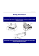
Safety Information Safety Information Never remove any printer cover unless it is necessary for the installation of a printer accessory and expressly described in this manual. Please retain the printer covers in a safe place because they should be reinstalled if you decide to remove any printer. The following areas of the printer should be covered for safety reasons: F ront C over (A S F) The above openings must always be protected with their cover when the corresponding option is not installed.
FCC Notes FCC Notes This equipment has been tested and found to comply with the limits for a Class B digital device, pursuant to Part 15 of the FCC Rules. These limits are designed to provide reasonable protection against harmful interference when the equipment is operated in a commercial environment. This equipment generates, uses and can radiate radio frequency energy and, if not installed and used in accordance with the instruction manual, may cause harmful interference to radio communications.
Table of Contents Table of Contents Leaving the Printer Setups ............................................ 37 Power on Configuration Setup........................................... 37 Entering the Power-On Configuration........................... 38 Program Setup ................................................................... 54 Entering the Program Setup.......................................... 54 Safety Information ...............................................iii FCC Notes......................
Getting to Know Your Printer Getting to Know Your Printer Printer Features 4051/4051N plus Common Features • • • • • • • • • 9 Needle Print Head Draft printing at 480 cps and in Letter Quality at 120 cps IBM Proprinter XL III, EPSON FX Series (ESC/P) emulation High resolution printing at 240 x 144 dots per inch Operator panel with a Liquid Crystal Display (16 alpha-numeric characters), three leds and eight function keys to control the operating printer state Easy usage through the Operator Panel and throu
Getting to Know Your Printer 4056/4056N plus Models Common Features • • • • • • • • • 24 Needle Print Head Draft printing at 480 cps and in Letter Quality at 133 cps IBM Proprinter XL24E, XL24E AGM, EPSON LQ 1050/2550 (ESC/P) emulation High resolution printing at 360 x 180 dots per inch Operator panel with a Liquid Crystal Display (16 alpha-numeric characters), three leds and eight function keys to control the operating printer state Easy usage through the Operator Panel and through software commands Prin
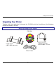
Getting to Know Your Printer Unpacking Your Printer Together with the Installation Guide and the CD-ROM with the User Manual, the following items are included in the box: Notify any damage to your supplier.
Getting to Know Your Printer Printer Parts 4051/4056 plus Models – Front View P rin ter C o ver D rive S e lection Le ver In terfac e B o ard C o ve r O p erato r Pa ne l P ap er T hickn ess Le ver 4
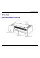
Getting to Know Your Printer 4051N/4056N plus Models – Front View Paper C hute Printer C over D rive S election Lever Interface Board C over Paper Thickness Lever O perator P anel 5
Getting to Know Your Printer All Models – Rear View Pow er S w itch Pow er S ocket Tractor C over 6 Interface S ocket R ear Paper Entry Slot
Setting Up Your Printer Setting Up Your Printer Choosing a Suitable Location Consider the following points when you choose the location for your printer: • The distance between the printer and the host computer must not exceed the length of the interface cable; • The location must be sturdy, horizontal and stable; • Your printer must not be exposed to direct sunlight, extreme heat, cold, humidity or dust see “Printer Specifications” section later; • You need a power outlet compatible with the plug of the p
Setting Up Your Printer Printer Assembly Ribbon Cartridge Installation It is advisable to insert the ribbon cartridge while the printer is turned off. However, your printer can be turned on during this procedure, but do not forget that it must be disabled to print (Wait displayed and READY led turned off). 1. Remove the printer cover by pressing simultaneously the two buttons in the front part of the cover.
Setting Up Your Printer 2. If you are inserting the ribbon cartridge for the first time, do not forget to complete the unpacking procedure by taking off the plastic hooks that fix the paper bail. 3. Pull the paper thickness lever towards the front of the printer to facilitate ribbon insertion.
Setting Up Your Printer 4. Remove the new ribbon cartridge from its bag. Remove and discard the holdfast (1) that blocks the ribbon. Turn the tension knob (2) to tighten the ribbon. 5. Insert the ribbon (1) between the print head (2) and the print head mask (3). Lay the cartridge over the printer carriage (4). Make sure that the two pins on each side of the cartridge are positioned over the retaining clips of the printer carriage.
Setting Up Your Printer 6. Push the cartridge gently down while turning the tension knob (1). Make sure that the cartridge clicks into place (2). 7.
Setting Up Your Printer 8. Replace the printer cover by first inserting the hooks (1) into the appropriate grooves (2) and then lower the cover ensuring that clicks in place. • If your printer is the 4051N plus or the 4056N plus model, simply lower the printer cover to close it. 9. Move the paper thickness lever according to the paper type: • If a cut sheet is loaded move the lever towards the back of the printer.
Setting Up Your Printer Paper Chute Installation (4051/4056 plus models only) The paper chute is provided with the 4051plus and 4056 plus printers. To install the paper chute in the printer follow this sequence: To insert the paper chute correctly, make sure that you are in front of the printer and that you hold the paper chute in the front position. 1. Insert the hook on the left side of the paper chute in the groove situated near the paper entry slot.
Setting Up Your Printer 2. Flex the paper chute towards the front of the printer and insert the hook on the opposite side of the paper chute in the corresponding groove. This printer accessory may assume two different positions according to the paper type: down position for fanfold paper (A) and raised position for cut sheet (B). 3. If you wish to position the paper chute down, lift it towards the back of the printer and push it gently down until it stops.
Setting Up Your Printer Host Computer Connection This printer can be connected to your host computer via two available interfaces. The interface connectors are located on the rear of the printer. • A bidirectional IEEE1284 parallel interface • A RS-232C/422A serial interface Make sure that both printer and host computer are switched off. Parallel Connection Insert the parallel interface cable into the parallel connector and fasten it by means of the clips.
Setting Up Your Printer Serial Connection Insert the serial interface cable into the serial connector, and fasten it by means of the two screws (use the screwdriver).
Setting Up Your Printer Software Driver Selection At this point it is necessary to configure your printer for your application package. The installation procedures depend upon the host environment: Follow the instructions in the readme file you find on the CD-ROM. In a WINDOWS® 95/98/2000 environment the printer supports the Plug & Play feature. The printer drivers of all Compuprint printers can be found at the Internet Address http://www.compuprint.
Setting Up Your Printer Power Connection Make sure that the power outlet matches the power rating of the printer. See the name plate of the printer, that you find in the rear of the printer. Always use a grounded outlet. Make sure that the power outlet is near the printer location and easily accessible. 1. Make sure that the power switch at the rear of the printer is in the "printer off" position. Insert one end of the power cable plug into the printer connector placed on the rear of the printer.
Setting Up Your Printer 2. Insert the other end of the power cable in a convenient outlet. 3. To turn the printer on, press the part of the power switch that now is up. The print head moves and stops at about 6.5 inches from the left side of the printer and the indicators on the operator panel light up for a few seconds. Every time the printer is turned off and you need to turn it on again, wait 3 seconds before turning it on.
Selecting the Display Language Selecting the Display Language The display messages for this printer can be displayed in two different languages: English (Default) and Italian. To select the language that you prefer, proceed as follows: 1. Enter the Power on Configuration procedure. • Make sure that the printer is turned off. • Keep the PROGRAM key pressed while you turn on the printer. After the initialization phase the following message will be displayed: INSTALLATION 2.
Configuring the Printer Configuring the Printer Operator Panel Presentation The operator panel consists of three elements: • Display: you can see on the display various messages usually regarding the printing functions. • Indicators: give information about the operating state of the printer. • Function keys: allow you to change operating state of the printer as necessary.
Configuring the Printer Basic Indications on the Display When turning the printer on, after the message 405x plus, the display indicates the printer status (Ready, Wait, Busy, Quiet), the current macro (M1, M2, M3, M4) and the selected emulation (IBM XL III or EPSON FX for the 4051/4051N plus printers and IBM XL 24E, IBM XL24 AGM and EPSON LQ for the 4056/4056N plus printers) as follows: Ready M1-EPS The following list shows you the status and error messages in alphabetical order: 1.Enable path SS 2.
Configuring the Printer Buffer cleared Displayed after input buffer clearing (all the stored data are erased). Call Service Displayed in rolling mode together with the failure message to indicate a call to Service. Carriage error Displayed when there is an unrecoverable carriage error. This means that the printer carriage does not move correctly. When the Carriage error message is displayed, the indicator READY blinks. Check that the ribbon cartridge is not used up neither damaged.
Configuring the Printer Fanfold thru ASF This is one of the messages that will be displayed when you press PATH (Shift function). Press the SHIFT key to select the handling of the fanfold paper with the Automatic Sheet Feeder (option) installed (4051/4056 plus models only). Initializing Displayed while the printer is turned on. Invalid keypress An invalid pressing of a key has occurred. Labels This is one of the messages that will be displayed when you press PATH (Shift function).
Configuring the Printer Quiet --- OFF Displayed when the Quiet function is not selected. Quiet --- ON Displayed when the Quiet function is selected. Ready M1-EPS Displayed when the printer is on line and ready to print. Release button Generic user intervention message. Remove paper Displayed when Eject operation is not successful. Self-test Displayed during the self test procedure. You can select the test procedure keeping pressed the ON LINE key while turning on the printer.
Configuring the Printer Indicators READY PROGRAM SHIFT Lit When the printer is enabled to receive and print data. Blinking The printer is unable to receive and print data (Wait message displayed) but there is still data in the input buffer. Unlit When the printer is unable to print because: • the test procedure is running; • the printer initialization is running. Lit When the PROGRAM function of the operator panel keys has been selected and enabled.
Configuring the Printer Function Keys Each key can select one of the three available function modes: Normal, Program or Shift. • The Normal function does not require previous action to be selected. • The Program function is selected by pressing the PROGRAM key when the printing is disabled. Keep pressed this key while turning on the printer until the message Release button is displayed, the Power on Configuration Setup will be entered.
Configuring the Printer ON LINE Key ON LINE Normal Function Pressing this key you will obtain different results depending on the printer status: • When the READY indicator is lit on, pressing this key you will cause the stop of the printing at the end of the current line; the READY indicator blinks if there is some data left in the Input buffer, otherwise the indicator is turned off and the Wait message will be displayed.
Configuring the Printer LOAD/PATH Key LOAD Normal Function If you press this key while the printer is unable to print you will obtain the following effects: • No action if paper is already present. The Invalid keypress will be displayed • If paper is not present, pressing this key, the paper is loaded according to the drive selection lever selection • PATH Shift Function If the optional ASF is installed, the paper is loaded from the selected ASF bin (4051/4056 plus models only).
Configuring the Printer FF/PARK Key FORM FEED Normal Function Pressing this key while the printer is offline causes: • The paper, if loaded, advances at new page or, if parked, is positioned on the first printable line. • The cut sheet, if loaded, is ejected (max. 21 inches) or a new cut sheet will be loaded. PARK ← Shift Function No action if the paper is not present. Invalid keypress message is displayed. Fanfold paper, present in the printer, is set in parking position. Parking paper is displayed.
Configuring the Printer LF/QUIET Key LINE FEED QUIET → Normal Function It is available when printing is disabled. This function causes a paper advancement to the next printable line. Keeping pressed this key for more than a second, you will obtain the continuous execution of paper advancing. Shift Function It allows a noise level reduction. Keeping pressed this key Quiet--OFF and Quiet--- ON will be displayed in rolling mode.
Configuring the Printer FONT Key ↑ FONT ↑ Normal Function The ↑ (MICRO FEED FORWARD) function is available when the printer is not printing and causes a forward micro feed of the paper. Keeping pressed this key for a second, the paper will advance in continuous mode at the speed of 3.5 ips (slew speed). Shift Function The Font function will be enabled. This function allows you to choose among the selectable fonts. Keeping pressed this key or pressing it within 1 second, the fonts will be scrolled.
Configuring the Printer PITCH Key ↓ PITCH ↓ Normal Function The ↓ function is available when the printing is not printing and allows to move backwards the paper with a micro advancement. Keeping pressed this key for a second, the paper moves backwards in continuous mode at the speed of 3.5 ips (slew speed). Shift Function The pitch function allows you to select the available horizontal spacing. Keeping pressed this key or pressing it within a second the spacings will be scrolled.
Configuring the Printer PROGRAM Key PROGRAM Normal Function Keeping pressed this key while you turn on the printer you will enter Power on Configuration Setup. Pressing this key when the printer is unable to print, (indicator READY unlit) you will enter the Program Setup and the Program Function of keys are enabled. The PROGRAM indicator is turned on when the function is enabled. Pressing this key when the PROGRAM indicator is turned on, the Program Function is disabled and the indicator turned off.
Configuring the Printer Buzzer This printer is provided with a buzzer to indicate particular conditions according to the problem detected: • 1 short "beep" (0,25 sec): the BEL code has been sent; when the buzzer sound stops, the printer returns to normal operation. • Continuous "beep": the printer cover has been raised when the printer is enabled to print. Close the cover and make sure that the message Wait (READY indicator unlit) is displayed before raising the cover again.
Printer Setups Printer Setups You can customize the printer depending on your needs via the Power on Configuration Setup and the Program Setup procedures. Entering the Printer Setups The PROGRAM key allows to enter the Printer Setups. • Keep pressed the PROGRAM key while powering the printer on to enter the Power on Configuration Setup. • Press the PROGRAM key when the printer is disabled (READY indicator unlit) to enter the Program Setup.
Printer Setups Leaving the Printer Setups Whenever you wish to leave the current Printer Setup, proceed as follows: • In the Power-On Configuration, press the PROGRAM key and the new settings will be automatically stored. The printer leaves the Power on Configuration Setup and is disabled to print (READY indicator unlit). • In the Program Setup, press the PROGRAM key and if any change occurred the message SAVE MACRO? will be displayed.
Printer Setups Entering the Power-On Configuration 1. Make sure that the printer is turned off. 2. Keep pressed the PROGRAM button key while turning on the printer. The 4051 plus, 4051N plus, 4056 plus or 4056N plus message will be displayed then Release button message. 3.
Printer Setups IBM Mode PROTOCOL ↑ IBM MODE → or ← ↓ EPSON MODE IBM C-SET (1/2) ↑ or ↓ → or ← IBM set... NATION ↑ or ↓ → or ← CP 437 ... 20 CPI ↑ or ↓ → or ← No IBM C-SET (1/2) IBM character sets selection. NATION IBM national character sets selection. 20 CPI IBM compressed printing selection. - IBM Character Sets 20 CPI ↑ IBM C-SET (1/2) → or ← IBM set 1 (*) ↑ or ↓ ↓ IBM set 2 ↑ or ↓ NATION IBM set 1 IBM CS1 character set selection. IBM set 2 IBM CS2 character set selection.
Printer Setups - IBM National Character Sets IBM C-SET (1/2) ↑ CP 437 (*) ↑ or ↓ ↓ ...
Printer Setups EPSON Mode PROTOCOL ↑ EPSON MODE → or ← ↓ NATION ↑ or ↓ → or ← USA EPSON C-SET ↑ or ↓ → or ← Italics .... LINE MODE NATION EPSON national character sets selection EPSON C-SET EPSON character sets selection. - EPSON National Character Sets EPSON C-SET ↑ NATION → or ← ↓ EPSON C-SET USA (*) ↑ or ↓ ...
Printer Setups The CP 858 and ISO 8859/15 character sets contain the Euro character. - EPSON Character Sets NATION ↑ EPSON C-SET → or ← Italic ↑ or ↓ ↓ Graphic 1 ↑ or ↓ Graphic 2 (*) ↑ or ↓ NATION Italic EPSON Italic character set selection. Graphic 1 EPSON Graphic 1 character set selection. Graphic 2 EPSON Graphic 2 character set selection.
Printer Setups LF=LF+CR If the printer receives a LF code, it performs a line feed followed by a carriage return. If the printer receives a CR code, it only performs a carriage return. LF&CR=LF+CR If the printer receives a LF code or a CR code, it performs both a line feed and a carriage return. Tear/View Mode LINE MODE ↑ TEAR/VIEW MODE ↓ LANGUAGE → or ← Auto.advance 1s (*) ↑ or ↓ ... ↑ or ↓ Auto.advance 5s ↑ or ↓ Manual advance ↑ or ↓ No tear ↑ or ↓ Auto.advance 1s ...
Printer Setups Display Language Selection TEAR/VIEW MODE ↑ LANGUAGE → or ← ↓ English (*) ↑ or ↓ Italiano ↑ or ↓ BUZZER This function selects the language of the display messages: in English or Italian language. Enable/Disable Buzzer LANGUAGE ↑ BUZZER ↓ → or ← Enabled (*) ↑ or ↓ Disabled ↑ or ↓ PROTOCOL This function enables or disables the buzzer.
Printer Setups INTERFACE Function Interface Type INSTALLATION HIGH GUARD LEVEL ↑ ↑ INTERFACE → or ← → or ← INTERFACE TYPE ↓ ↓ PRINT STATUS I/F TIME-OUT Automatic (*) ↑ or ↓ Parallel ↑ or ↓ Serial ↑ or ↓ Automatic The interface type is automatically selected according to the data transmission. Parallel Parallel interface selection. Serial Serial interface selection. Interface Time-out INTERFACE TYPE ↑ I/F TIME-OUT ↓ INPUT BUFFER → or ← 2 seconds (*) ↑ or ↓ ...
Printer Setups Input Buffer Size I/F TIME-OUT ↑ INPUT BUFFER → or ← ↓ PARALLEL MODE 256 (DLL) ↑ or ↓ ... ↑ or ↓ 32K (No DLL) (*) ↑ or ↓ This function selects the input buffer size with one of the following values: 256, 4K, 8K, 16K or 32 K. The 16K and the 32K values do not allow the DLL. The most suitable value for the DLL function is 256 (DLL).
Printer Setups AUTOFEED Signal PARALLEL MODE ↑ AUTOFEED SIGNAL → or ← ↓ Enabled ↑ or ↓ Disabled (*) ↑ or ↓ SLCT-IN SIGNAL Enabled The parallel interface uses the AUTOFEED signal. Disabled The parallel interface ignores the AUTOFEED signal. SELECT-IN Signal AUTOFEED SIGNAL ↑ SLCT-IN SIGNAL ↓ → or ← Disabled (*) ↑ or ↓ Enabled ↑ or ↓ SERIAL TYPE Enabled The parallel interface uses the SELECT-IN signal. Disabled The parallel interface ignores the SELECT-IN signal.
Printer Setups Serial Interface Type SLCT-IN SIGNAL ↑ SERIAL TYPE → or ← ↓ RS232C (*) ↑ or ↓ RS422A ↑ or ↓ SERIAL MODE This function selects the serial interface type: RS-232/C or RS-422/A. Serial Connection Mode SERIAL TYPE ↑ SERIAL MODE ↓ → or ← Local (*) ↑ or ↓ Remote ↑ or ↓ BAUD RATE This function selects the serial connection type: local or remote.
Printer Setups Baud Rate SERIAL MODE ↑ BAUD RATE → or ← ↓ WORD LENGTH 600 bps ↑ or ↓ ... ↑ or ↓ 9600 bps (*) ↑ or ↓ ... ↑ or ↓ 38400 bps ↑ or ↓ This function selects the data transmission speed in bits per second (bps). The values available are: 600, 1200, 2400, 4800, 9600, 19200, 38400. Data Format BAUD RATE ↑ WORD LENGTH ↓ → or ← 7 bit ↑ or ↓ 8 bit (*) ↑ or ↓ PARITY BIT This function selects the data format, using 7 or 8 bits.
Printer Setups Parity Check WORD LENGTH ↑ → or ← PARITY BIT ↓ BUFFER CONTROL Even ↑ or ↓ Odd ↑ or ↓ Mark ↑ or ↓ Space ↑ or ↓ None (*) ↑ or ↓ Even Parity check is enabled for even parity. Odd Parity check is enabled for odd parity. Mark Parity check disabled and the transmitted parity bit is always in Mark state. Space Parity check disabled and the transmitted parity bit is always in Space state. None Parity check (for 8 data bits only).
Printer Setups Robust XON BUFFER CONTROL ↑ ROBUST XON → or ← ↓ No (*) ↑ or ↓ Yes ↑ or ↓ HIGH GUARD LEVEL This function selects the execution of Robust XON. High Guard Level ROBUST XON ↑ HIGH GUARD LEVEL → or ← 10% Buffer Size ↑ or ↓ ↓ ... ↑ or ↓ 90% Buffer Size (*) ↑ or ↓ INTERFACE TYPE Selects the percentage of the input buffer to fix to the High Guard Level signal.
Printer Setups PRINT STATUS Function • Press the → key to select the function. The message Printing test will displayed while the following output will be printed: 405x plus: OPTIONS FONT DRAFT MODE. VERTICAL PITCH LPI LOCK FORM LENGTH TOP MARGIN BOTTOM MARGIN HORIZONTAL PITCH CPI LOCK LEFT MARGIN RIGHT MARGIN SLASHED ZERO MULTICOPY PRINT DIRECTION CONTROLLER:78XXXXXX Rel.:x.xx GENERATOR: 78XXXXXX Rel.:x.
Printer Setups RECALL FACTORY Function • Press the → key to select this function. The values of the functions return to the factory default setting. All values of the functions are reset to the factory default ones in both Power on Configuration Setup and Program Setup. These are the default values: OPTIONS FONT DRAFT MODE.
Printer Setups Program Setup The default values are marked with an asterisk (*). These are the available functions: SELECT MACRO This function defines four different macros and allows to configure the printer for different job types. PRINT ADJUSTMENT This function allows the adjustment of the mechanical parameters and the tuning of the first printing line. PRINT STATUS This function allows to print the current printer configuration.
Printer Setups SELECT MACRO Function MACRO SELECTION HEXADECIMAL DUMP MACRO 4 ↑ ↑ SELECT MACRO → or ← MACRO 1 ↓ ↓ PRINT ADJUSTMENT MACRO 2 → or ← FONT ↑ or ↓ DRAFT MODE ↑ or ↓ VERTICAL PITCH ↑ or ↓ LPI LOCK ↑ or ↓ FORM LENGTH ↑ or ↓ TOP MARGIN ↑ or ↓ BOTTOM MARGIN ↑ or ↓ HORIZONTAL PITCH ↑ or ↓ CPI LOCK ↑ or ↓ LEFT MARGIN ↑ or ↓ RIGHT MARGIN ↑ or ↓ SLASHED ZERO ↑ or ↓ MULTICOPY ↑ or ↓ PRINT DIRECTION ↑ or ↓ This function allows to select one of the four available pri
Printer Setups Font Selection PRINT DIRECTION ↑ FONT → or ← Draft (*) ↓ DRAFT MODE ↑ or ↓ ... ↑ or ↓ OCR-B ↑ or ↓ Selects the type of character to use: Draft, Courier, Gothic, OCR-A, OCR- B for the 4051/4051N plus models and Draft, Courier, Gothic, Prestige, Presentor, OCR-A, OCR-B, Script, Boldface for the 4056/4056N plus models. OCR-A and OCR-B may be selected only when the nonproportional pitch is selected. Boldface may be selected only when the proportional pitch is selected.
Printer Setups Vertical Spacing DRAFT MODE ↑ VERTICAL PITCH → or ← ↓ LPI LOCK 6 lpi (*) ↑ or ↓ ... ↑ or ↓ 12 lpi ↑ or ↓ 3 lp/30 mm ↑ or ↓ ... ↑ or ↓ 12 lp/30 mm ↑ or ↓ This function determines the density with which the lines are printed according to different units: lines printed per inch (6, 8, 12 lpi) or lines per 30 mm (3, 4, 6, 8, 12 lp/30 mm).
Printer Setups Form Length LPI LOCK ↑ FORM LENGTH → or ← ↓ TOP MARGIN NUMBER OF LINES ↑ or ↓ A4 (11.6 inches) A5 (8 inches) → or ← 1 line (*) ↑ or ↓ ↑ or ↓ ... ↑ or ↓ ↑ or ↓ 126 lines ↑ or ↓ This function selects the physical page length in n° of lines (1 to 126 lines at 1/6”) or in standard formats (A4 or A5). Top Margin FORM LENGTH ↑ TOP MARGIN ↓ BOTTOM MARGIN → or ← Line #1 (*) ↑ or ↓ ...
Printer Setups Bottom Margin TOP MARGIN ↑ BOTTOM MARGIN → or ← ↓ HORIZONTAL PITCH Line #1 ↑ or ↓ ... ↑ or ↓ Line #66 (*) ↑ or ↓ ... ↑ or ↓ Line #126 ↑ or ↓ This function selects the bottom margin defined as n° of lines (at 1/6”). The value X corresponds to the n° of lines set in the FORM LENGTH function. Horizontal Spacing BOTTOM MARGIN ↑ HORIZONTAL PITCH ↓ CPI LOCK → or ← 5 cpi ↑ or ↓ ... ↑ or ↓ 10 cpi (*) ↑ or ↓ ... ↑ or ↓ 20 cpi ↑ or ↓ Prop.
Printer Setups Cpi Lock HORIZONTAL PITCH ↑ → or ← CPI LOCK ↓ Enabled ↑ or ↓ Disabled (*) ↑ or ↓ LEFT MARGIN Enabled Horizontal spacing is selected only by operator panel (PITCH key). Disabled Horizontal spacing is selected by the operator panel (PITCH key) or by software. Left Margin CPI LOCK ↑ LEFT MARGIN ↓ RIGHT MARGIN → or ← Column#1 (*) ↑ or ↓ ...
Printer Setups Right Margin LEFT MARGIN ↑ RIGHT MARGIN → or ← ↓ SLASHED ZERO Column#1 ↑ or ↓ ... ↑ or ↓ Column#136 (*) (4051/4056 plus models) ↑ or ↓ Column#100 (*) (4051N/4056N plus models) ↑ or ↓ This function sets the right margin defined as number of columns. The physical margin position depends on the selected horizontal spacing.
Printer Setups Multicopy Form SLASHED ZERO ↑ MULTICOPY → or ← ↓ Yes ↑ or ↓ No (*) ↑ or ↓ PRINT DIRECTION This function selects the printing on multicopy format paper (Yes) or on normal paper (No). Print Direction MULTICOPY ↑ PRINT DIRECTION ↓ FONT → or ← Unidirectional ↑ or ↓ Bidirectional ↑ or ↓ Soft. control (*) ↑ or ↓ This function selects the print direction: unidirectional, bidirectional o controlled by software.
Printer Setups PRINT ADJUSTMENT Function Bidirectional Print Alignment SELECT MACRO. TEAR PERFO ALIGN ↑ ↑ PRINT ADJUSTMENT → or ← BIDI. ALIGNMENT ↓ ↓ PRINT STATUS TOP OF FORM → or ← Offset: +6 ↑ or ↓ ... ↑ or ↓ Offset: -6 ↑ or ↓ This function adjusts the bidirectional printing in a range between - 6 and +6. When the previous value is changed, the printer prints two ‘|’ lines to control the final output.
Printer Setups Top of Form (ToF) BIDI. ALIGNMENT ↑ TOP OF FORM ↓ TEAR PERFO ALIGN → or ← 0/72 inches (4051/4051N plus models) ↑ or ↓ 0/90 inches (4056/4056N plus models) ↑ or ↓ ... ↑ or ↓ 792/72 inches (4051/4051N plus models) ↑ or ↓ 990/90 inches (4056/4056N plus models) ↑ or ↓ This function adjusts the top of the form in n/72 inch (4051/4051N plus models) or n/90 inch (4056/4056N plus models).
Printer Setups Tear Position Alignment TOP OF FORM ↑ TEAR PERFO ALIGN ↓ BIDI. ALIGNMENT → or ← 0/72 inches (4051/4051N plus models) ↑ or ↓ 0/90 inches (4056/4056N plus models) ↑ or ↓ ↑ or ↓ ... 36/72 inches (4051/4051N plus models) ↑ or ↓ 45/90 inches (4056/4056N plus models) ↑ or ↓ This function adjusts the tear off position in n/72 inch (4051/4051N plus models) or n/90 inch (4056/4056N plus models).
Printer Setups PRINT STATUS Function • Press the → key to select the function. The message Printing test will displayed while the following output will be printed: 405x plus: OPTIONS FONT DRAFT MODE. VERTICAL PITCH LPI LOCK FORM LENGTH TOP MARGIN BOTTOM MARGIN HORIZONTAL PITCH CPI LOCK LEFT MARGIN RIGHT MARGIN SLASHED ZERO MULTICOPY PRINT DIRECTION CONTROLLER:78XXXXXX Rel.:x.xx GENERATOR: 78XXXXXX Rel.:x.
Printer Setups HEX DUMP Function This function may be selected at any point of the printing. To activate the hexadecimal printing follow this sequence: 1. After entering the Program Setup, select the following item: HEXADECIMAL DUMP 2. Press the → key to activate this function. Press the ↓ key, the following messages will be alternatively displayed. HEX DUMP OFF HEX DUMP ON 3. Release the ↓ key when the Hex dump ON message is displayed, to confirm this selection, press → key.
Paper Handling Paper Handling Paper Specifications Use the correct paper in your printer for obtaining good results in your printout.
Paper Handling Cut Sheets Minimum 102 mm (4 inches) Maximum 420 mm (16.6 inches) Length Minimum 63,5 mm (2.5 inches) Weight Minimum 50 g/m2 Maximum 120 g/m2 Width Number of copies 1 original plus 5 carbon copies Weight: First and last sheets Other sheets Carbon paper Total thickness Minimum 55 g/m2 Maximum 75 g/m2 Minimum 45 g/m2 Maximum 75 g/m2 Minimum 14 g/m2 Maximum 35 g/m2 Maximum 0,52 mm (0.
Paper Handling Cut Sheets Cut sheets are inserted from the top of the printer. You can load manual cut sheet whether fanfold paper is inserted or not. If no fanfold paper is present, proceed as follows; otherwise, go to "Switching From Fanfold Paper to Cut Sheet" section. Loading Cut Sheets 1. Put the paper chute in the raised position by pulling and hooking it firmly. • If your printer is the 4051N plus or the 4056N plus model, simply lift the paper chute that is fixed in the printer cover.
Paper Handling • If your printer is the 4051plus or the 4056 plus model and you wish to position the first printing column at 25 mm from the edge of the paper, slide the left paper guide to the left as far as it will go, then adjust the right paper guide according to the paper width. 2. Move the paper thickness lever according to the type of paper: • If a cut sheet is loaded move the lever towards the back of the printer.
Paper Handling 3. If the printer is turned off, turn the printer on. The display shows Load Paper, if there is no paper in the printer. If you turn the printer on when paper is already inserted, the display will show Remove Paper while buzzer sounds 4 short "beeps". The paper is ejected with a backward movement of maximum 24 inches. If you have not removed the paper yet, the buzzer will sound again 4 short “beeps”. Finally the display will show Load paper. 4. Feed the cut sheet in the slot.
Paper Handling Fanfold Paper The fanfold paper must be inserted at the rear of the printer. Inserting Fanfold Paper 1. Put the paper chute in the raised position by lifting and hooking it firmly. • If your printer is the 4051N plus or the 4056N plus model, lift the paper chute that is inserted in the printer cover.
Paper Handling 2. Open the tractor cover until it clicks into place. 3. Unlock the sprocket on the side of the interface connector and, if it is not already positioned, slide it to the right until it stops.
Paper Handling 4. If you wish the first column in a particular position, the ruler under the tractor should be helpful to position the sprocket. The distance between the marks on the ruler is 1/10 inch. 5. Lock the sprocket in place. 6. Unlock the other sprocket and position it in accordance with the paper width. Slide the spacers evenly along the tractor bar.
Paper Handling 7. Open the sprocket covers. 8. Position the holes in the paper over one sprocket and then over the other.
Paper Handling 9. Close the sprocket covers. 10. Adjust the two sliders on the tractor cover in alignment with the spacers and close the cover firmly.
Paper Handling • If your printer is the 4051 plus or the 4056 plus model, put the paper chute in the down position by lifting it towards the back of the printer and pushing gently down until it stops. Space the paper guides evenly on the paper chute 11. Place the drive selection lever in the fanfold position (fanfold drawing) and make sure that Fanfold is selected by pressing PATH key (SHIFT function) on the operator panel. 12.
Paper Handling Parking Fanfold Paper Whenever you wish to park the fanfold paper, follow the sequence: 1. Make sure that the printer is disabled to print (Wait message is displayed and the READY indicator is unlit) and tear the fanfold paper that is currently loaded along the last perforation. 4051/4056 plus Models 4051N/4056N plus Models 2. Press the SHIFT key and then the PARK key to enable the PARK function.
Paper Handling Switching From Fanfold Paper to Cut Sheet If you have been using fanfold paper and you have not removed it, your printer allows the cut sheet loading after performing a parking of the inserted fanfold paper (PARK function). 1. Make sure that your printer is turned on and disabled to print (READY indicator unlit). Tear the fanfold paper that is currently loaded along the last perforation. 4051/4056 plus Models 4051N/4056N plus Models 2.
Paper Handling Top of Form Adjustment The Top of Form Adjustment procedure allows you to adjust the position of the first printable line and therefore it is advisable to perform it immediately after a paper loading. Turn the printer on, if it is not, and proceed as follows: Make sure that the printer is not printing. (READY indicator unlit). If the fanfold paper has been loaded, park it by pressing the PARK key. If the cut sheet has been inserted, eject it by pressing the FF key. 1. Press the PROGRAM key.
Paper Handling Tear Off Line Adjustment The Tear Off Line Adjustment procedure allows you to adjust the position of the fanfold perforation in order to tear it against the printer tear off border on the cover. This procedure is available only if the Program Setup is previously entered. The Tear Off Line Adjustment procedure can be executed at any time during the printing. Proceed as follows. 1. Make sure that the printer is not enabled to print (READY indicator unlit and the message Wait displayed). 2.
Printer Maintenance and Troubleshooting Printer Maintenance and Troubleshooting Cleaning the Printer Make sure that the printer has been turned off for at least 15 minutes before any cleaning intervention. Periodical cleaning will help to keep your printer in top condition. • • • Use a neutral detergent or a water solution on a soft cloth to clean dirt and grease from the cabinet of the printer.
Printer Maintenance and Troubleshooting Replacing the Ribbon Cartridge If the printing is fading, the ribbon could be worn or damaged. It is advisable to remove the used ribbon cartridge while the printer is turned off. However, your printer can be turned on during this procedure, but do not forget that it must be disabled to print (Wait message displayed). Make sure that the new ribbon cartridge is an original Compuprint spare part.
Printer Maintenance and Troubleshooting 2. Move the printer carriage to the center of the printer. 3. Lift the cartridge off until the clip release it. Now, you are ready to insert a new ribbon cartridge. Follow from step 2 of "Ribbon Cartridge Installation" section.
Printer Maintenance and Troubleshooting Printing the Self Test It is advisable to print the self-test printout to inform you about the current printer configuration and to check if the printer is working well. Then, proceed as follows: 1. Keep the ON LINE key pressed while you turn the printer on, the display will show the following message: Printing test The message Printing test will remain displayed while the following output will be printed 2. Press ON LINE key to stop printing.
Printer Maintenance and Troubleshooting Error Handling The following table will help you to identify and solve problems which may occur when using the printer. If the problem is not listed, or if it is not corrected by any of the methods suggested, contact your supplier for help. Problem Cause Solution Printer fails to print Wait is displayed Press ON LINE key to enable printing. Interface cables are not properly connected Push cables firmly into sockets at both ends.
Printer Maintenance and Troubleshooting Problem Cause Solution Dark, smudgy print Print head too close to paper Pull paper thickness lever towards the front of the printer to move print head away from paper. Self-test not printed ON LINE key not pressed while Repeat the sequence (see “Printing the Self Test “ turning the printer on. before). Carriage fault Press ON LINE key and repeat the sequence (see “Printing The Self Test” before).
Options Options LAN Connection For the 4051/4056 printer models, an integrated Ethernet 10/100 Base-T interface for the network connections is available that coexists with the serial interface. For more information, refer to the Installation Guide you receive together the “PRINTER SERVER ETHERNET 10/100 Mbit Multiprotocol” CD-ROM.
Options Automatic Sheet Feeder (4051/4056 plus models only) This Automatic Sheet Feeder (ASF) provides fast and automatic feeding of cut sheets and multicopy-forms on your printer. This option is quickly and easily installed onto the printer by the operator. No tools or special equipment are necessary. Operation of the sheet feeder is relatively simple and with proper installation and care, it will provide long and trouble-free service.
Options Preparing the Printer Make sure that no paper is present in the printer and that the Automatic Sheet Feeder loading is selected via your printer operator panel (see “Configuring the Printer” section). 1. Turn the printer off. 2. Remove the printer cover by pushing down simultaneously the two buttons in the front part of the cover and lifting it out.
Options 3. Remove the paper chute, if present, as follows: • put it in the raised position and flex it towards the front of the printer; • lift the right side of the paper chute; • unhook the left side of the paper chute. Keep the printer cover and the paper chute in a safe place as they must be reinstalled if the ASF is removed.
Options 4. Slide the rubber rollers (1) of the paper bail to the extreme right side. Remove the plastic mask (2) that protects the feeding mechanism on the right side of the platen. 1 1 5. Put the drive selection lever in the cut sheet position.
Options Automatic Sheet Feeder Assembly 1. Find the paper stackers. 2. Clip two paper stackers (1) onto the metal strip (2), placed over the paper entry slot (3), for the input of paper.
Options 3. Clip the other two paper stackers (4) onto the metal strip (5), placed over the paper sorter (6), for the output of paper. 4 5 6 4. Find the paper sorter cover.
Options 5. Lay the upper locking groove (1) of the paper sorter cover (3) on the upper internal pin (2) placed in the paper sorter. Rotate the paper sorter cover towards the front of the printer.
Options 6. Click the paper sorter cover into place. If you have the optional second bin, install it now on your ASF as follows: • Remove the cover plates (1) from the rear of the first bin.
Options • Insert the second bin into the first bin of ASF, ensuring that the two support arms (2) snap in place. 2 Remember that once you have placed the second bin, it is not possible to separate it from the first bin. 7. Hold the ASF parallel to the platen and slightly tilted towards the front of the printer. Fit the hooks (1) into the small bars (2) at either side of the platen. Release the ASF.
Options 8. Find the front cover. 9. Slide the front cover (1) under the ASF and then push it down until it clicks in place.
Options Paper Specifications The following specifications should be adhered to in order to assure reliable feeder operation. See the following tables: Cut Sheet Width Length Weight Storage Minimum 85,4 mm (6 inches) Maximum 381 mm (15 inches) Minimum (Bin 1) 145 mm (5.
Options Multi-part Forms Pressure Sensitive Paper Carbon Paper Maximum 2 copies First Sheet 70 - 80 g/m2 Copies 40 - 60 g/m2 Last Sheet 70 - 80 g/m2 Maximum 2 copies First Sheet 70 - 80 g/m2 Copies 35 - 40 g/m2 Last Sheet 70 - 80 g/m2 Carbon Paper 25 g/m2 The uncovered surface of the carbon paper has to be rough. Envelopes Width Length Thickness Minimum 127 mm (5 inches) Maximum 254 mm (10 inches) Minimum 101 mm (4 inches Maximum 160 mm (6.5 inches) Minimum 0.10 mm (0.
Options Paper Loading Make sure that all preliminary operations of preparing the printer are executed, then follow the sequence: 1. Open the paper bin by moving the slider (1) up in OPEN position.
Options 2. Unlock the left paper guide (2) by moving the paper guide lever (3) up. Move the paper guide towards the desired position.
Options 3. Unlock the right paper guide (2) by moving the paper guide lever (3) up.
Options 4. Fan the paper thoroughly. 5. Stack the paper firmly in the bin. Adjust the right paper guide to the correct paper width and ensuring that the paper is not too close in the bin. Lock both paper guides by moving the paper guide levers down.
Options Bin Bin 1 Bin 2 Output Stacker Capacity 100 Cut Sheets 35 Multi-part Forms 100 Cut Sheets 35 Multi-part Forms 150 Cut Sheets 50 Multi-part Forms Weight 80 g/m2 80 g/m2 80 g/m2 6. Close the paper bins by moving the slider down in CLOSED position. • Whenever the bin is opened, reposition the paper in the bin. • Whenever the printer received a print command, it automatically performs a paper loading.
Options Switching From Fanfold Paper to ASF If you have been using fanfold paper and the printer receives a command to load a cut sheet through the Automatic Sheet Feeder: 1. Park the fanfold paper: press the SHIFT key and then the PARK key to enable the PARK function, the message Parking paper will be displayed. 2. Place the drive selection lever in the cut sheet position. Press the ON LINE key. Inserting Manual Cut Sheets Without Removing the ASF Follow the sequence: • Open the paper bins.
Options Using Fanfold Paper through Automatic Sheet Feeder Your printer allows to load the fanfold paper with the Automatic Sheet Feeder (option) installed. The paper width must be maximum 15 inches (381 mm) and it is advisable to test it so that this feature can be correctly performed. Follow the sequence: 1. Make sure that the fanfold paper is in parking position and that the printer is idle. 2. Press the SHIFT key and then PATH key.
Options How to Keep the Automatic Sheet Feeder Clean Your Automatic Sheet Feeder has been designed to operate reliably over a long period of time with minimal care and attention. However, it is advisable: • Remove the dust from the ASF by first removing it from the printer. To remove dust and paper particles from the ASF you should use a soft brush.
Options 2. Remove the front cover. Then remove the ASF by tilting it slightly towards the front of the printer and lifting it off. 3. Position the rubber roller (1) in their places evenly along the paper bail. Fix the plastic mask (2) again. 1 1 4. Replace the printer cover and the paper chute.
Options Problem Solving The following table will help you to identify and solve problems which may occur when using the ASF. If the problem is not listed, or if it is not corrected by any of the methods suggested, contact your supplier for help. Problem Cause Solution The ASF does not feed the paper The paper bin(s) not in operating position. Set paper bin(s) to correct operating position. The platen movement is not being transferred to ASF. Check the ASF mounting and proper gear contact.
Printer Specifications Printer Specifications Printing Characteristics Print Head Matrix Needles Diameter Print Head Life 4051/4051N plus 4056/4056N plus 9 needles 24 needles 0.30 0.
Printer Specifications Throughput (page/hour) 4051/4051N plus 4056/4056N plus HS Draft 390 390 Draft 370 370 4051/4051N plus 4056/4056N plus Print Matrix (horizontal per vertical) HS Draft 10 cpi 10 x 9 9 x 24 Draft 10 cpi 12 x 9 12 x 24 12 cpi 10 x 9 10 x 24 15 cpi 10 x 9 8 x 16 17.1 cpi 12 x 9 12 x 24 20 cpi 12 x 9 12 x 24 10 cpi 20 x 18 36 x 24 12 cpi 20 x 18 30 x 24 15 cpi 20 x 18 24 x 16 17.
Printer Specifications Print Density (characters per inch) Normal 10 - 12 - 15 Expanded 5 - 6 - 7.5 -8.55 Compressed 17.1 - 20 Proportional Line Length (number of characters) 4051/4056 plus 4051N/4056N plus 136 at 10 cpi 100 at 10 cpi 163 at 12 cpi 120 at 12 cpi 204 at 15 cpi 150 at 15 cpi 233 at 17.1 cpi 171 at 17.
Printer Specifications Resident Fonts 4051/4051N plus: Draft, Courier, Gothic, OCR-A, OCR-B 4056/4056N plus: Draft, Courier, Gothic, OCR-A, OCR-B, Boldface, Prestige, Script, Presentor Print Attributes Subscript (*), Superscript (*), Underline (*), Overscore, Italics (*), Emphasized, Double Strike, Compressed Double Width, Double Height Note: (*) Graphic characters do not accept this attribute Graphic Resolution (dots per inch) 4051/4051N plus 4056/4056N plus Horizontal 60, 72, 80, 90, 120, 144, 240 60
Printer Specifications Character Sets ASCII Normal + Slanted (italics) IBM PC Character Sets CS1 and CS2 EPSON National Variations USA, France, Germany, United Kingdom, Denmark-1, Sweden, Italy, Spain-1, Japan, Norway, Denmark-2, Spain-2, Latin America.
Printer Specifications Paper Handling Copies 1+ 5 Thickness 0.52 mm max. Size Fanfold Width: 76 to 406 mm (3’’ to 16’’) for 4051/4056 plus models Width: 76 to 305 mm (3” to 12”) for 4051N/4056N plus models Cut Sheet Width: 102 to 420 mm (4’’ to 16,6”) Height: 63 to 304 mm (2.5’’ to 12’’) Paths Fanfold Rear Push Cut Sheet Manual Front Labels on Fanfold or Cut Sheet Envelopes Manual Front or through the ASF Reverse Movement on all paper types (max.
Printer Specifications Physical and Electrical Characteristics Interfaces Parallel I/F IBM-Epson and Centronics compatible Bidirectional, IEEE 1284 Buffer: up to 32 KBytes Nibbles and Byte Mode Shared w/ DLL buffer 7/8 data bits max 100 KBPS Serial I/F RS-232/C and 422/A 600 to 38400 baud bps 7/8 data bits DTR XON/XOFF Break Buffer : up to 32 KBytes Shared w/ DLL buffer Automatic Interface Switching 118
Printer Specifications Reliability MTBF Mean Time Between Failure: 10000 hours @ 25% Duty Cycle Print Head (Draft) 400 MC Ribbon (Draft) 3 MC Power Supply 220/240 Volt - 50 Hz Noise level 4051/4051N plus: 55 dBA 4056/4056N plus: 54 dBA Physical Dimensions 4051/4056 plus 4051N/4056N plus Height 173 mm (6,7 “) 186 mm (7,3”) Width 615 mm (24,2”) 520 mm (20,4”) Depth 310 mm (12,2”) 310 mm (12,2”) Weight 15 kg 13 kg 119
Environment Conditions Storage Conditions Temperature -40° to 50° C Relative Humidity 10%t o 90% RH (non condensing) Operating Conditions Temperature 10° to 38° C Relative Humidity 10% to 90% RH (non condensing) Paper Conditions Temperature 16° to 24° C Relative Humidity 40% to 60% RH (non condensing) Options (for 4051/4056 plus models only) LAN Interface Board (factory installation) Automatic Sheet Feeder - ASF (user installation) Standard Compliance ESD IEC 801-2 GS/EN 60950 (included IT Power Syst