
Printer User Manual
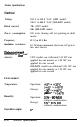
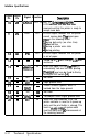
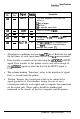
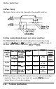
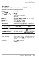
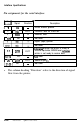

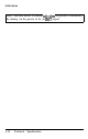
Table Of Contents
- ADDENDUM
- FRONT MATTER
- TABLE OF CONTENTS
- ABOUT THIS MANUAL
- INTRODUCTION
- CHAP 1-SETTING UP THE PRINTER
- CHAP 2-PAPER HANDLING
- CHAP 3-USING THE PRINTER
- CHAP 4-SOFTWARE AND GRAPHICS
- CHAP 5-USING THE PRINTER OPTIONS
- CHAP 6-MAINTENANCE
- CHAP 7-TROUBLESHOOTING
- CHAP 8-TECHNICAL SPECIFICATIONS
- CHAP 9-COMMAND SUMMARY
- APPENDIX
- INDEX
- QUICK REFERENCE
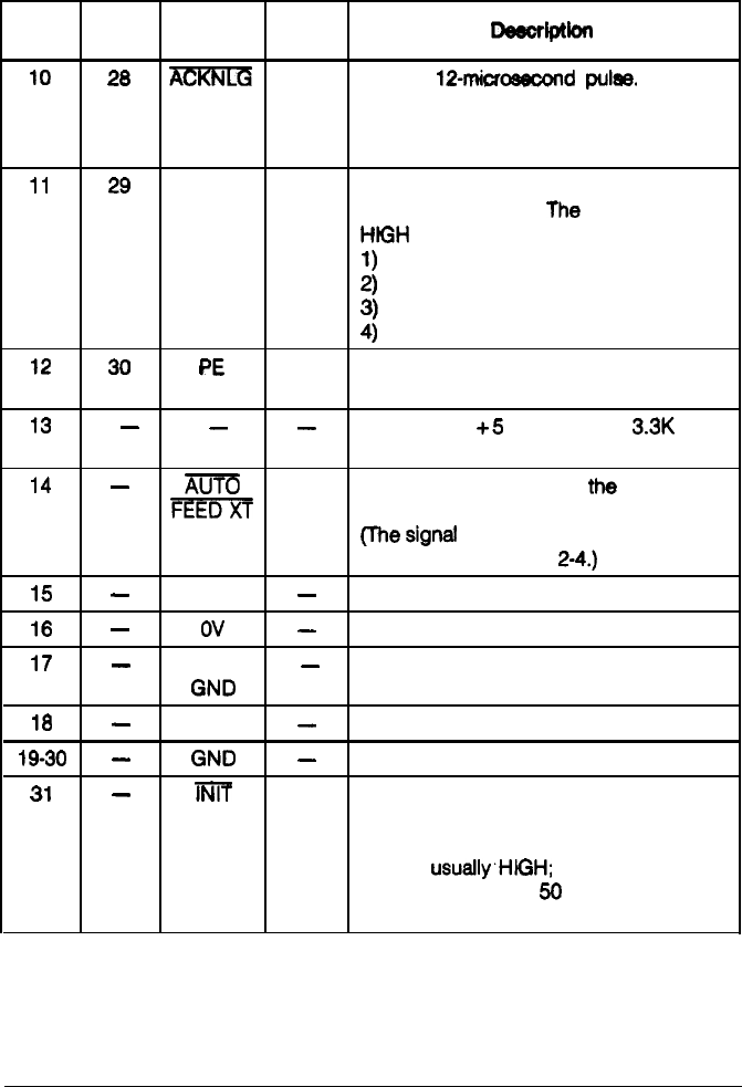
Interface Specifications
Signal Return
Pin Pin
Signal Direction
-lptiofl
10
28
m
OUT About a
1Pmicrosecond
pulse.
LOW
indicates that data has been
received and that the printer is ready to
accept more data.
11
29 BUSY OUT
A HIGH signal indicates that the printer
cannot receive data.
The
signal goes
HtGH
in the following cases:
1)
during data entry (ea. char. time)
2)
when off
line
12
30
PE
3)
during a printer error state
4)
during printing
OUT
A HIGH signal indicates that the printer
is out of paper.
13
-
-
-
Pulled up to
+5
volts through
3.3K
ohm
resistance.
14
-
m
IN
When this signal is LOW,
the
paper
is
FEED
automatically fed one line after printing.
(The
signal
level can be fixed to this by
turning on DIP switch
2-4.)
15
-
NC
-
Not used.
16
-
ov
-
Logic ground level.
17
-
CHASSIS
-
Printer’s chassis ground, which is
GND
isolated from the logic ground.
18
-
NC
-
Not used.
19-30
-
GND
-
Twisted-pair return signal ground level.
31
-
lNlf
IN
When this level becomes LOW, the
printer controller is reset to its power-up
state and the print buffer is cleared. This
level is
usually~H/GH;
its pulse width
must be more man
56
microseconds at
the receiving terminal.
8-12
Technical Specifications