DM-D110 Technical Reference guide EPSON English 410826900 Rev.
DM-D110 Technical Reference Guide CAUTIONS ❏ This document shall apply only to the product(s) identified herein. ❏ No part of this document may be reproduced, stored in a retrieval system, or transmitted in any form or by any means, electronic, mechanical, photocopying, recording, or otherwise, without the prior written permission of Seiko Epson Corporation. ❏ The contents of this document are subject to change without notice. Please contact us for the latest information.
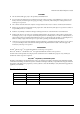
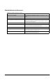
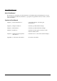
Related Software and Documents Related software and documents ii Software/document name Description DM-D110 User’s Manual/ This provides basic handling procedures for the end user of the printer DM-D110 Technical Reference Guide This Manual ESC/POS Application Programming Guide This provides descriptions in Acrobat format of the commands used by each TM printer, along with sample programs and other information about the printers EPSON OPOS ADK This is a OCX driver EPSON OPOS ADK Manual This pro
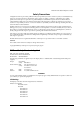
DM-D110 Technical Reference Guide Safety Precautions All rights reserved. No part of this publication may be reproduced, stored in a retrieval system, or transmitted in any form or by any means, electronic, mechanical, photocopying, recording, or otherwise, without the prior written permission of Seiko Epson Corporation. No patent liability is assumed with respect to the use of the information contained herein.
FCC Compliance Statement For American Users This equipment has been tested and found to comply with the limits for a Class A digital device, pursuant to Part 15 of the FCC Rules. These limits are designed to provide reasonable protection against harmful interference when the equipment is operated in a commercial environment.
DM-D110 Technical Reference Guide ❏ Never disassemble or modify this product. Tampering with this product may result in injury or fire. ❏ Be sure to use the specified power source. Connection to an improper power source may cause fire. ❏ Do not allow foreign matter to fall into the equipment. Penetration by foreign objects may lead to fire. ❏ If water or other liquid spills into this equipment, unplug the power cord immediately, and then contact your dealer or a Seiko Epson service center for advice.
About This Manual Aim of the Manual This manual was created to provide information on the DM-D110 customer display for anyone who is developing hardware, installations, or programs. Programmers will also want to consult other documents. Contents of the Manual vi Chapter 1, “General Information.” General description of features plus specifications. Chapter 2, “Setup information.” Describes product DM-D110 setup. Chapter 3, “DIP Switches.” Describes product DIP Switch settings. Chapter 4, “Hardware.
DM-D110 Technical Reference Guide Contents Revision Information . . . . . . . . . . . . . . . . . . . . . . . . . . . . . . . . . . . . . . . . . . . . . . . . . . . . . . . . . . . . . . . . . . . . . . . . . . . . Related Software and Documents . . . . . . . . . . . . . . . . . . . . . . . . . . . . . . . . . . . . . . . . . . . . . . . . . . . . . . . . . . . . . . EMC and Safety Standards Applied . . . . . . . . . . . . . . . . . . . . . . . . . . . . . . . . . . . . . . . . . . . . . . . . . . . . . .
Chapter 5 Application Development Information Introducing the Control Methods . . . . . . . . . . . . . . . . . . . . . . . . . . . . . . . . . . . . . . . . . . . . . . . . . . . . . . . . . . . . . . . . . Commands . . . . . . . . . . . . . . . . . . . . . . . . . . . . . . . . . . . . . . . . . . . . . . . . . . . . . . . . . . . . . . . . . . . . . . . . . . . . . . . . Driver . . . . . . . . . . . . . . . . . . . . . . . . . . . . . . . . . . . . . . . . . . . . . . . . . . . . . . . . . . . . . . . .
DM-D110 Technical Reference Guide Chapter 1 General Information 1.1 Features The DM-D110 has the following features. ❏ Large amounts of data can be displayed on the 20-column × 2-line dot matrix. ❏ The display uses a fluorescent light, so it is easy to see at a wide angle in bright places and dark places.*1 The fluorescent light has a long life. ❏ The emitting light color is green and the brightness can be adjusted by an ESC/POS command.
1.2 Installation Example The DM-D110 can be attached to the EPSON HSS series and TM printers, and it can be attached to a DM-D stand. 1.3 Connection Example 1.3.1 Pass-through Connection The pass through connection is the way of connecting the TM printer with the cash drawer by passing through the stand of the customer display by using one serial port of the host personal computer. Host PC TM printer DM-D110 + DP-110 PS-180 Cash Drawer Power cable 1-2 General Information Rev.
DM-D110 Technical Reference Guide 1.3.2 Stand-Alone Connection One serial port of the host personal computer is used as the exclusive port of the customer display. Host PC DM-D110 + DP-110 PS-180 Power cable TM printer Cash Drawer When [Serial Port3 Mode] of the SR-610 is set [DRW/DM-D], the customer display and the cash drawer can be controlled by COM3. 1.3.
1.4 System Requirements ❏ A personal computer having a serial I/F ❏ A TM printer having a DM-D connector ❏ EPSON HSS series 1.5 System Planning A customer display can display and be controlled using any of the following three methods: 1. ESC/POS commands 2. EPSON OPOS ADK 3. Windows printer driver (EPSON Advanced Printer Driver) Refer to the "Application development information" in Chapter 5 from the characteristics of each. 1-4 General Information Rev.
DM-D110 Technical Reference Guide Chapter 2 Setup information 2.1 Cautions on Handling When you use the DM-D110, be sure to note the following points: ❏ Avoid locations that are subject to high temperature and humidity. ❏ Avoid dirty and dusty locations. ❏ Avoid locations that are unstable or are subject to high levels of vibration. ❏ When connecting or disconnecting cables, make sure that the power switch of the DM-D110 and printers connected to the DM-D110 are turned off.
2.3 Accessories DP-110-1x1 DP-110-1x2 DP-502 DP-503 DP-504 DP-505 extension cable for power supply 1 - - - - - RS-232C connector installation screw (mm type) 4 - - - - - fixing topping screw (M3 X 10) - - 2 3 - - fixing screw (M3 X 5) - - 2 - - - fixing screws for wood position (M3.
DM-D110 Technical Reference Guide 2.4.1.1 Required items The following items are used to attach the DM-D110 to the DM-D stand. The power supply unit (PS-180) and the extension support (DP-105) are options. For details, ask your dealer. DM-D stand extension cable for power supply interface connector base plate RS-232C connector installation screw (mm type) Velcro tapes power supply unit (PS-180) extension support Rev.
2.4.1.2 Connectors for the DP-110-1x1 The connectors for the DP-110-1x1 are as follows: display connector computer connector power supply unit connector printer connector extension cable connector Note: Inch-type hexagonal lock screws are installed in the RS-232 connector. If millimeter-type lock screws are needed, use the millimeter-type lock screws of the accessory. notch (one or more lines) inch-type millimeter-type RS-232C connector installation screw 2.4.1.
DM-D110 Technical Reference Guide 2.4.1.4 Precautions on using the power supply unit To avoid damage to the DM-D110 and the power supply unit, make sure to note the following points. ❏ Use the optional Seiko Epson products, PS-180 as the power supply. ❏ Never connect the DC cable to the power supply unit when the power supply unit is connected. ❏ Unplug the DC cable by holding the connector part. If you pull the cable to unplug it, it may be damaged. 2.4.1.5 Assembling steps 1.
2. Insert the tab on the DM-D110 (or the extension support) into the hole on the DM-D stand until you feel it click. 3. When connecting to a TM printer with a Y-type connection, skip to step 13. Connect the cable for the DM-D110 to the display connector on the DM-D stand until you feel it click. 2-6 Setup information Rev.
DM-D110 Technical Reference Guide 4. Connect one end of the interface cable to the computer connector inside the DM-D stand and connect the other end to the RS-232 connector of the host personal computer. Tighten the screws on both ends of the cables to fasten them. computer 5. When using as a standalone, go to step 7.
6. When not using the extension cable for the power supply packed with the DM-D stand, go to step 7. When using the extension cable, connect it (with the arrow mark up) to the extension cable connector indicated by “POWER OUT” on the DM-D stand; then connect the other end to the power connector on the printer. extension cable connector extension cable for power supply 7.
DM-D110 Technical Reference Guide 9. Arrange the cables as shown below. Put the cables for the DM-D110 inside the DM-D stand. 10. Attach the base plate to the DM-D stand following the numbered arrows shown below. Then push the base plate until it is locked by the hook on the DM-D stand. 1 2 11. When the extension support (DP-105) is used, attach Velcro tapes to the four corners of the plate to keep the unit from falling down. 12. Connect the cord of the power unit to the socket.
14. Set the DIP switch of the DM-D110 and switch the communication speed as follows. (Refer to Chapter 3 doe details of the DIP switch setting.) Communication speed: 19200bps Communication data length: 8Bit Parity: Off 15. Attach the base plate to the DM-D stand following the numbered arrows shown below. Then push the base plate until it is locked by the hook on the DM-D stand. 1 2 16.
DM-D110 Technical Reference Guide 2.4.2 Attaching to the TM-H6000 Series/TM-U675 The DM-D110 can be attached directly to the TM-H6000II/TM-U675 printers using the “DM-D pole unit for TM printers (Type A)” (DP-502). You can attach fixing plate A on either side of the TM-H6000II/TM-U675. After attaching it, you can slide the display freely. 2.4.2.1 Required items The following items are used to attach the DM-D110 to the TM-H6000II/TM-U675 printers.
2.4.2.2 Assembling steps 1. Pass the cable for the DM-D110 through support C, and attach support C to the DM-D110. When using support B for extension, insert the tab on support B into the hole on support C until you feel it click. When using support B for extension 2. Attach the rubber feet to the printer. 3. Attach fixing plate B to the printer. 2-12 Setup information Rev.
DM-D110 Technical Reference Guide 4. Pass the cable for the DM-D110 through the hole on fixing plate A, and fix the cable at the bottom as shown below. 5. Connect the cable for the DM-D110 to the DM connector on the TM printer. 6. Attach fixing plate A to the TM printer using the stopper. When you attach the stopper, insert the projections on the stopper into the holes of fixing plate B. Fixing plate A can be attached on either side of the printer.
7. The horizontal rotation mechanism of fixing plate A can be adjusted. To secure the location of the display, set fixing plate A to either one of the following four positions and secure it with the angle fixing screw. 2-14 Setup information Rev.
DM-D110 Technical Reference Guide Note: The paper roll cover may not open if the position of the display is incorrect. Before securing the position of the display, make sure that you can open the paper roll cover. paper roll cover 8. Store any excess cable in the support and attach the DM-D110 to fixing plate A. 9. Connect the power cable of the printer. To avoid disconnection, hook the cable on the tabs on fixing plate B, as shown below. Rev.
2.4.3 Attaching to the TM-H5000 Series/TM-J8000 The DM-D110 can be attached directly to the TM-H5000II/TM-J8000 printers using the “DM-D pole unit for TM printers (Type B)” (DP-503). 2.4.3.1 Required items The following items are used to attach the DM-D110 to the TM-H5000II /TM-J8000 printers. These items are packed with the “DM-D pole unit for TM printers (Type B)” (DP-503). fixing screws base support A support B (for extension) 2.4.3.2 Assembling steps 1.
DM-D110 Technical Reference Guide 2. Attach the base to the setting position on the TM printer and secure it with the screws. 3. Pass the cable for the DM-D110 through the base. 4. Insert the tab on the base into the hole on the support until you feel it click. 5. Connect the cable for the DM-D110 to the DM connector on the TM printer. Rev.
2.4.4 Attaching to the TM-U950 The DM-D110 can be attached directly to the TM-U375/TM-U950 printers using the “DM-D pole unit for TM printers (Type A)” (DP-502). 2.4.4.1 Required items The following items are used to attach the DM-D110 to the TM-U375/TM-U950 printers. These items are packed with the “DM-D pole unit for TM printers (Type A)” (DP-502).
DM-D110 Technical Reference Guide 2.4.4.2 Assembling steps 1. Pass the cable for the DM-D110 through support C and attach support C to the DM-D110. When using support B for extension, insert the tab on support B into the hole on support C until you feel it click. When using support B for extension 2. Attach the rubber feet to the printer. [TM-U950] Rev.
3. Pass the cable for the DM-D110 through the hole on fixing plate A and fix the cable at the bottom as shown below. 4. Connect the cable for the DM-D110 to the DM connector on the TM printer. 5. Adjust the length of the cable and secure fixing plate A to the printer with screws. [TM-U950] 2-20 Setup information Rev.
DM-D110 Technical Reference Guide 6. Store any excess cable in the support, and attach the DM-D110 to fixing plate A. 2.4.5 Attaching to Other TM Printers When using with other TM printers, the DM-D110 can be attached to a desk or other surface, using the “DM-D pole unit for TM printers (Type A)” (DP-502), and Velcro tapes or screws. 2.4.5.1 Required items The following items are used when the DM-D110 is used with other TM printers.
2.4.5.2 Assembling steps using Velcro tapes 1. Attach Velcro tapes to the bottom of fixing plate A. 2. Pass the cable for the DM-D110 through support C and attach support C to the DMD110. When using support B for extension, insert the tab on support B into the hole on support C until you feel it click. When using support B for extension 2-22 Setup information Rev.
DM-D110 Technical Reference Guide 3. Pass the cable for the DM-D110 through the hole on fixing plate A, and fix the cable at the bottom as shown below. 4. Connect the cable for the DM-D110 to the DC connector on the TM printer. 5. Store any excess cable in the support, and attach the DM-D110 to fixing plate A. 6. Peel off the Velcro tapes and attach the display as shown above.. Rev.
2.4.5.3 Assembling steps using screws 1. Follow steps 2 and 3 in “Assembling steps using Velcro tapes.” 2. Secure fixing plate A to the setting position with fixing screws. 3. Attach the DM-D110 to fixing plate A. 2-24 Setup information Rev.
DM-D110 Technical Reference Guide Chapter 3 DIP Switches The DIP switches configure the communication settings and whether a self-test is required. 3.1 DIP Switches Two DIP switches are located on the back of the display panel. The following table shows the functions of each switch. Functions: Refer to the tables below. The DIP switch settings are read only when the power is turned on. Therefore, changing the settings while the power is on has no effect. DSW1 No.
3.1.2 Setting the DIP switches CAUTION: Remove the cable of the DM-D110 before removing the DIP switch cover to prevent electrical damage to the DM-D110. 1. Remove the cable of the DM-D110. 2. Remove the DIP switch cover. ON 1 2 3 4 5 6 7 8 DIP switch cover 3. Change each setting of the switches with a pointed object, such as a pen tip or small screwdriver. Close the cover and connect the cable to computer. 3-2 DIP Switches Rev.
DM-D110 Technical Reference Guide Chapter 4 Hardware 4.1 Interface Signal Connection Diagram The illustration below shows the signal connections of the interface: DP-110-1x1 Rev.
4.2 Data Flow 4.2.1 Pass-through Connection With the pass-through connection, the command from one serial port of the host personal computer is transmitted through the DM-D stand to control the DM-D110, the printer and the drawer. The data flow which is connected through the DM-D stand is as follows.
DM-D110 Technical Reference Guide 4.2.2 Standalone Connection With the standalone connection, the command from the serial port of the host personal computer is transmitted directly to control the DM-D110. The data flow when the standalone connection is as follows.
4.2.3 Y-type Connection With the Y-type connection, the command from the serial/USB port of the host personal computer is transmitted through the printer to control the DM-D110 and the cash drawer. The data flow when the DM-D110 is connected with the Y-type connection is as follows.
DM-D110 Technical Reference Guide 4.2.4 DM-D110 Standard Model Interface Connectors Type: RJ-45 Connector 4.2.4.1 Display interface connector pin assignments Display interface connector pin assignments Pin Number Signal Name Signal Direction Signal Function 1 FG — Frame ground 2 TXD Output (1) When the DM-D110 is connected with a pass-through or Y-type connection: Transmits data to the printer. (2) When the DM-D110 is connected as a standalone: Transmits data to the host.
4.3 DM-D110 and PC Connection Cable The host interface connector connects the host computer to the DM-D110 standard model via the DM-D stand. Type: D-SUB 25-pin connector (female type) The optional stand provides the host interface connector shown in the figure below. 4.3.0.
DM-D110 Technical Reference Guide 4.3.1 DP-110 Printer Interface Connector The printer interface connector connects a standard model DM-D110 to the printer via the DM-D stand. Type: D-SUB 9-pin connector (male type) The optional stand provides the printer interface connector shown in the figure below. 4.3.1.
4.3.2 DP-110 Power Supply Connector The base unit of the DM-D stand provides two power supply connectors. One is used for the input terminals from the external power supply and the other is used to supply power to the printer. Both connectors have the same electrical characteristics (signal functions, signal direction, signal level). These connectors can be used for the DM-D110 power supply connector to the display interface board or the power supply connector to the printer.
DM-D110 Technical Reference Guide Chapter 5 Application Development Information This chapter describes how to control the customer display. 5.1 Introducing the Control Methods 5.1.1 Commands ❏ ESC/POS commands ESC/POS commands directly control the customer display and control all the functions of it. However, detailed knowledge of the hardware, control, and operating environment is required and you need to code all the functions for yourself.
5.1.3.2 Operating environment ❏ Supported OS (Operation checked) • Windows2000 Professional SP4 or later • Windows XP Professional SP2 or later See OPOS release notes for the latest information. ❏ Supported development language • Visual Basic • VisualC++ 5.1.4 Features of Windows Driver (EPSON (EPSON Advanced Printer Driver) Driver) EPSON Advanced Printer Driver is a Windows driver for the display function of the customer display.
DM-D110 Technical Reference Guide 5.2 Selecting Environment and Driver Select the driver for the customer display depending on your environment. Windows environment .net environment When you develop a new application. Use OPOS. When you already use OPOS with an existing application. When you already use the APD with an existing application. Use OPOS. Rev. A Use OPOS. (The APD and OPOS cannot both be in one PC. Use OPOS also for the TM printer.) Environment other than .
5-4 Application Development Information Rev.
DM-D110 Technical Reference Guide Appendix A Character Code Tables A.1 Page 0 (PC437: U.S.A., standard Europe) (international character set: U.S.A.) Page 0 Indicated characters (00H-7FH) Note 1: Character codes from 00H (hexadecimal) to 7FH (hexadecimal) for each page are the same. Note 2: Some characters indicated by character codes from 00H to 7FH are changed by selecting the international character set. Refer to Section 4.3.13, International character set, for details. Rev.
Page 0 Indicated Characters (80H?FFH) Appendix A-2 Character Code Tables Rev.
DM-D110 Technical Reference Guide A.2 Page 1 (Katakana) Page 1 Indicated Characters (80H-FFH) Rev.
A.3 Page 2 (PC850: multilingual) Page 2 Indicated Characters (80H-FFH) Appendix A-4 Character Code Tables Rev.
DM-D110 Technical Reference Guide A.4 Page 3 (PC860: Portuguese) Page 3 Indicated Characters (80H-FFH) Rev.
A.5 Page 4 (PC863: Canadian-French) Page 4 Indicated Characters (80H-FFH) Appendix A-6 Character Code Tables Rev.
DM-D110 Technical Reference Guide A.6 Page 5 (PC865: Nordic) Page 5 Indicated Characters (80H-FFH) Rev.
A.7 Page 16 (WPC1252) Page16 Indicated Characters (80H-FFH) Appendix A-8 Character Code Tables Rev.
DM-D110 Technical Reference Guide A.8 Page 17 (PC866: Cyrillic2) Page17 Indicated Characters (80H-FFH) Rev.
A.9 Page 18 (PC852: Latin2) Page18 Indicated Characters (80H-FFH) Appendix A-10 Character Code Tables Rev.
DM-D110 Technical Reference Guide A.10 Page19 (PC858: Euro) Page19 Indicated Characters (80H-FFH) Rev.
A.11 Page254 (Space) Page254 Indicated Characters (80H-FFH) Appendix A-12 Character Code Tables Rev.
DM-D110 Technical Reference Guide A.12 Page255 (Space) Page255 Indicated Characters (80H-FFH) UD: undefined Rev.
A.13 International character set International characters listed in Table 4.3.14 can be changed by using the ESC R command. Refer to the description of the ESC R command in Section 5.3, Command Details. ASCII code (Hex) Country 23 24 40 5B 5C 5D 5E 60 7B 7C 7D 7E U.S.A # $ @ [ ¥ ] ^ ` { | } ~ France # $ à ° ç § ^ ` é ù è ¨ Germany # $ § Ä Ö Ü ^ ` ä ö ü ß U.K.