English EPSO N DM -D Read Series y EPSO N DM -D Se ries Read y Customer Display DM-D110-xx2 USB I/F User’s Manual 404930300
CAUTIONS ❏ This document shall apply only to the product(s) identified herein. ❏ No part of this document may be reproduced, stored in a retrieval system, or transmitted in any form or by any means, electronic, mechanical, photocopying, recording, or otherwise, without the prior written permission of Seiko Epson Corporation. ❏ The contents of this document are subject to change without notice. Please contact us for the latest information.
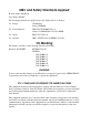
EMC and Safety Standards Applied Product Name: DM-D110 Type Name: M58DC The following standards are applied only to the display that is so labeled. ❏ Europe: CE Marking Safety: EN60950 ❏ North America: EMI: FCC/ICES-003 Class A Safety: UL 60950/CSA C22.2 No.
FOR CANADIAN USERS This Class A digital apparatus complies with Canadian ICES-003. Cet appareil numérique de la classe A est conforme à la norme NMB-003 du Canada.
English Important Safety Instructions This section presents important information intended to ensure safe and effective use of this product. Read this section carefully, and store it in an accessible location. Key to Symbols The symbols in this manual are identified by their level of importance, as defined below. Read the following carefully before handling the product. WARNING: Warnings must be followed carefully to avoid serious bodily injury.
❏ If water or other liquid spills into this equipment, immediately pull out the connection cable to the computer and contact your DM-D110 dealer or a SEIKO EPSON service center for advice. Continued usage may lead to fire or shock. CAUTION: 2 ❏ Do not plug the cable differently from the instruction in this manual. Wrong connection may cause equipment damage and fire. ❏ Be sure to set this equipment on a firm, stable, horizontal surface. Product may be damaged or cause injury if it falls.
Important Safety Instructions . . . . . . . . . . . . . . . . . . . . . . . . . . . . . . . . . . . . . . . . . . Key to Symbols . . . . . . . . . . . . . . . . . . . . . . . . . . . . . . . . . . . . . . . . . . . . . . . . . . . Safety Precautions . . . . . . . . . . . . . . . . . . . . . . . . . . . . . . . . . . . . . . . . . . . . . . . . Contents . . . . . . . . . . . . . . . . . . . . . . . . . . . . . . . . . . . . . . . . . . . . . . . . . . . . . . . . . . . . Handling Guidelines . . . . . . . . .
Handling Guidelines The DM-D110 is a compact customer display. The DM-D110-xx2 is the USB I/F specification and can connect with a USB port of a personal computer. The characteristics of the DM-D110-xx2 are shown below. ❏ Interface is USB I/F ❏ Supports Window XP and Windows 2000. *1 ❏ Design matches EPSON TM printers and IM series. ❏ Possible to set up the “DM-Dstand” or attach the unit to an EPSON TM printer with any installation option, such as the extension pole.
English Part Names DIP switch (rear side of the display) display Connection cable USB connector Unpacking The following items are in the box. installation manual DM-D110 Make sure that you have all the items shown above, and that none has been damaged. If you find that there are any missing or damaged items, please contact your DM-D110 dealer.
Setup The setup of the DM-D110 follows these steps. Download the driver Download the "USB RS-232 convert driver" from the EPSON web site and store it in your personal computer. Attaching the DM-D110 Attach DM-D110 to the stand or one of the printers. s DM-D Stand TM-H6000II/ TM-U675 TM-H5000II/ TM-J8000 TM-U375/ TM-U950 Setting the DIP switch When the transfer rate is different from that of the driver, remove the cable and change the setting of the DIP switch.
The “USB RS-232 convert driver” is necessary to use the DM-D110-xx2 USB I/F. This can be obtained from one of the following URLs. http://www.epson-pos.com/ (Japan, Europe, and other countries not listed below) http://pos.epson.com/ (USA/Canada and North America) Create a folder on the computer and store the downloaded driver. This driver must be installed to all computers which use USB I/F. This driver supports Window XP and Windows 2000. Usage The DM-D110 can be used with the following equipment.
Cautions on Handling When you use the DM-D110, be sure to note the following points: ❏ Avoid locations that are subject to high temperature and humidity. ❏ Avoid dirty and dusty locations. ❏ Avoid locations that are unstable or are subject to high levels of vibration. ❏ Do not drop the DM-D110 because you may damage the built-in vacuum fluorescent display. Attaching to the DM-D stand The DM-D110 can be attached directly to the DM-D stand using the “DM-D stand unit for DM Customer Display” (DP-110).
1. Pass the cable for the DM-D110 through the DM-D stand. When extending the length of the DM-D stand, attach the extension pole unit(DP-105) to the DM-D stand. When using the extension pole unit (DP-105) 2. Insert the tab on the DM-D110 (or the extension pole) into the hole on the DM-D stand until you feel it click. 3. Attach the base plate to the DM-D stand following the number of the arrow shown below. At this time, push the base plate until it is locked by the hook on the DM-D stand.
4. Connect the USB connector of the DM-D110 to the USB port of the computer. Computer 5. Arrange the cables. Put the cables for the DM-D110 inside the DM-D stand. 6. When the extension pole unit (DP-105) is used, attach Velcro tapes to the four corners of the plate to keep the unit from falling down. Attaching to the TM-H6000II/TM-U675 The DM-D110 can be attached directly to TM-H6000II/TM-U675 printers using the “DM-D pole unit for TM printers (Type A)” (DP-502).
Assembling steps 1. Pass the cable for the DM-D110 through support C, and attach support C to the DM-D110. When using support B for extension, insert the tab on support B into the hole on support C until you feel it click. When using support B for extension 2. Attach the rubber feet to the printer. 3. Attach fixing plate B to the printer. 11 English CAUTION: Be sure that you do not connect the cable of the DM-D110 to the USB port of the printer.
4. Pass the cable for the DM-D110 through the hole on fixing plate A, and fix the cable at the bottom as shown below. 5. Attach fixing plate A to the TM printer using the stopper. When you attach the stopper, insert the projections on the stopper into the holes of fixing plate B. Fixing plate A can be attached on either side of the printer. (The illustration below shows fixing plate A attached to the right side of the printer.) 6. The horizontal rotation mechanism of fixing plate A can be adjusted.
13 English
Note: The paper roll cover may not open if the position of the display is inappropriate. Before securing the position of the display, make sure that you can open the paper roll cover. paper roll cover 7. Connect the USB connector of the DM-D110 to the USB port of the computer. Computer CAUTION: Be sure that you do not connect the cable of the DM-D110 to the USB port of the printer. 8. Store any excess cable in the support, and attach the DM-D110 to fixing plate A.
The DM-D110 can be attached directly to the TM-H5000II/TM-J8000 printers using the “DM-D pole unit for TM printers (Type B)” (DP-503). The USB connector of the DM-D110 is connected to the USB port of the computer. Required items The following items are used to attach the DM-D110 to the TM-H5000II /TM-J8000 printers. These items are packed with the “DM-D pole unit for TM printers (Type B)” (DP-503).
2. Attach the base to the setting position on the TM printer and secure it with the screws. 3. Pass the cable for the DM-D110 through the base. 4. Insert the tab on the base into the hole on the support until you feel it click.
English 5. Connect the USB connector of the DM-D110 to the USB port of the computer. Computer CAUTION: Be sure that you do not connect the cable of the DM-D110 to the USB port of the printer. Attaching to the TM-U375/TM-U950 The DM-D110 can be attached directly to the TM-U375/TM-U950 printers using the “DM-D pole unit for TM printers (Type A)” (DP-502). The USB connector of the DM-D110 is connected to the USB port of the computer.
CAUTION: Be sure that you do not connect the cable of the DM-D110 to the USB port of the printer. Assembling steps 1. Pass the cable for the DM-D110 through support C and attach support C to the DM-D110. When using support B for extension, insert the tab on support B into the hole on support C until you feel it click. When using support B for extension 2. Attach the rubber feet to the printer.
4. Attach the secure fixing plate A to the printer with screws. [TM-U375] [TM-U950] 5. Connect the USB connector of the DM-D110 to the USB port of the computer. Computer 19 English 3. Pass the cable for the DM-D110 through the hole on fixing plate A and fix the cable at the bottom as shown below.
CAUTION: Be sure that you do not connect the cable of the DM-D110 to the USB port of the printer. 6. Store any excess cable in the support, and attach the DM-D110 to fixing plate A. Attaching to Other TM Printers When using with other TM printers, the DM-D110 can be attached to a desk or other surface, using the “DM-D pole unit for TM printers (Type A)” (DP-502), and Velcro tapes or screws. The USB connector of the DM-D110 is connected to the USB port of the computer.
In the case when the TM printer has the USB port, don't connect it with the TM printer. Assembling steps using Velcro tapes 1. Attach Velcro tapes to the bottom of fixing plate A. 2. Pass the cable for the DM-D110 through support C and attach support C to the DM-D110. When using support B for extension, insert the tab on support B into the hole on support C until you feel it click. When using support B for extension 3.
4. Connect the USB connector of the DM-D110 to the USB port of the computer. Computer CAUTION: Be sure that you do not connect the cable of the DM-D110 to the USB port of the printer. 5. Store any excess cable in the support, and attach the DM-D110 to fixing plate A. Assembling steps using screws 1. Follow steps 2 and 3 in “Assembling steps using Velcro tapes.” 2. Secure fixing plate A to the setting position with fixing screws. 3. Attach the DM-D110 to fixing plate A.
The “USB RS-232 convert driver” is necessary to use the DM-D110-xx2 USB I/F. This driver is composed of “USB high Speed Serial Converter” and “USB Serial Port.” Both of them must be installed. Installing the driver (Windows XP) 1. Confirm that the driver is stored in the appropriate folder of the computer. 2. Power on the computer and start Windows XP and quit all applications. 3. Connect the DM-D110-xx2 to the USB connector of the computer. 4. First install “USB high Speed Serial Converter”.
6. “Completing the Found New Hardware Wizard“ is displayed. Click [Finish]. 7. Next install “USB Serial Port”. “Welcome to the Found New Hardware Wizard“ is displayed. Choose [Install from a list of specific location] and click [Next]. 8. “Please choose your search and installation options.“ is displayed. Select [Search for the best driver in these locations] and enter the place where the downloading driver is stored. Click [Next].
English 9. “Completing the Found New Hardware Wizard“ is displayed. Click [Finish]. Confirmation of the operation Confirm that the installation was normal. 1. Select [Control Panel] from the Start menu; then double click [System]. On the Hardware tab, click {Device Manager]. 2. “System properties” is displayed. Select [Hardware] and click [Device Manager].
3. “Device Manager” is displayed. Confirm that [USB high Speed Serial Converter] and [USB Serial Port] are present. 4. Confirm that the cursor is displayed on the display screen of the DM-D110. Uninstalling the driver (Windows XP) The uninstallation process of the “USB RS-232 convert driver” is as follows. 1. Quit all applications and disconnect the DM-D110 from the USB connector. 2. Execute “Ftdiunin.exe.” (In the downloaded and stored folder.) 3. “FTDI Uninstaller Version2.1” is displayed.
English Installing the driver (Windows 2000) 1. Confirm that the driver is stored in the appropriate folder of the computer. 2. Power on the computer and start Windows 2000 and quit all applications. 3. Connect the DM-D110-xx2 to the USB connector of the computer. 4. First install “USB high Speed Serial Converter”. The Setup starts and “Welcome to the Found New Hardware Wizard” is displayed. Click [Next]. 5. “Install Hardware Device Drivers“ is displayed.
6. “Locate Driver Files“ is displayed. Select [Specify a location] and click [Next]. 7. The following dialog is displayed. Enter the place where the downloaded driver is stored and click [OK]. 8. “Driver Files Search Results“ is displayed. Click [Next]. 9. “Completing the Found New Hardware Wizard” is displayed. Click [Finish].
English 10. Next install “USB Serial Port”. The Setup starts and “Welcome to the Found New Hardware Wizard” is displayed. Click [Next]. 11. “Install Hardware Device Drivers“ is displayed. [Search for a suitable driver for my device] and click [Next]. 12. “Locate Driver Files“ is displayed. Select [Specify a location] and click [Next].
13. The following dialog is displayed. Enter the place where the downloading driver is stored and click [OK]. 14. “Driver Files Search Results“ is displayed. Click [Next]. 15. “Completing the Found New Hardware Wizard” is displayed. Click [Finish]. Confirming the operation Confirm that the installation was normal. 1. Select [Settings]-[Control Panel]-[System] from the Start menu of Windows.
English 2. “System Properties“ is displayed. Select [Hardware] and click [Device Manager]. 3. “Device Manager” is displayed. Confirm that [USB high Speed Serial Converter] and [USB Serial Port] are present. 4. Confirm that the cursor is displayed on the display screen of the DM-D110. Uninstalling the driver (Windows 2000) The uninstallation process of the “USB RS-232 convert driver” is as follows. 1. Quit all applications and disconnect the DM-D110 from the USB connector. 2. Execute “Ftdiunin.exe”.
3. “FTDI Uninstaller Version2.1” is displayed. Click [Continue]. 4. The following dialog is displayed. Click [Finish]. DIP Switch DIP Switch Functions The DM-D110 has one DIP switch. The functions of the DIP switch are as follows: DIP switch 1 DSW1 No.
SW1-5 SW1-6 SW1-7 Transmission speed (bps) ON ON ON 2400 OFF ON ON 4800 ON OFF ON 9600 OFF OFF ON 19200 ON ON OFF 38400 OFF ON OFF 57600 ON OFF OFF 115200 OFF OFF OFF reserved English Transmission speed Setting the DIP switches CAUTION: Remove the cable of the DM-D110 before removing the DIP switch cover to prevent electrical damage to the DM-D110. 1. Remove the cable of the DM-D110. 2. Remove the DIP switch cover. ON 1 2 3 4 5 6 7 8 DIP switch cover 3.
Operation There is no power switch on the DM-D110-xx2. Connect the USB connector to the computer or start the computer to which the DM-D110-xx2 is connected. When the power is on, the cursor appears on the display. Turning and tilting the DM-D110 You can turn or tilt the display while holding the support. The display can be moved easily, so do not move any further if it stops. If you move it by force, you may damage it.
The DM-D110 has a self test function. If you want to perform a self test, you must change the setting of the DIP switch. Check Items of Self test The following items are checked during the self test: ❏ Control ROM version ❏ DIP switch settings ❏ Memory switch settings ❏ Example of display characters ❏ Example of each function, such as brightness, flashing, and scroll Performing Self test To perform the self test, follow the steps below. 1.
Specifications General Specifications Vacuum fluorescent display Character Specifications Number of characters 40 (20 columns x 2 lines) Display color Green (505 nm) Brightness 690 ( cd/m2) Type of character Character grid Alphanumeric characters 95 International characters 37 Extended graphics 128 characters x 12 pages Font 5 x 7 dot matrix, cursor Character size 3.5mm x 5.0mm Character pitch 5.
English Dimensions ❏ Height, Width, Depth and Weight DM-D110 DM-D stand (DP-110) • • DM-D110: Height x Width x Depth: Weight: 69 x 165 x 50.
DM-D pole unit for TM printers (Type A) (DP-502) DM-D pole unit for TM printer (Type B) (DP-503) 248 mm 260 mm 164 mm 78 mm 50 mm base 53 mm 38 • Base and support C of the “DM-D pole unit for TM printers (Type B)” (DP-503): Height x Width x Depth: 248 x 50 x 53 mm Weight: 116 g • Fixing plate A and support C of the “DM-D pole unit for TM printers (Type A)” (DP-502): Height x Width x Depth: 260 x 78 x 164 mm Weight: 264 g