DM-D210 Installation Guide 401467600
English All rights reserved. No part of this publication may be reproduced, stored in a retrieval system, or transmitted in any form or by any means, electronic, mechanical, photocopying, recording, or otherwise, without the prior written permission of Seiko Epson Corporation. No patent liability is assumed with respect to the use of the information contained herein.
English Safety Precautions This section presents important information intended to ensure safe and effective use of this product. Read this section carefully, and store it in an accessible location. WARNING: Shut down your equipment immediately if it produces smoke, a strange odor, or unusual noise. Continued use may lead to fire or electric shock. Immediately turn the power off and contact your dealer or a SEIKO EPSON service center for advice. Never attempt to repair this product yourself.
English Unpacking The items shown in illustration 1 are in the box. 1 installation manual display (DM-D210) Make sure that you have all the items shown, and that none has been damaged. If you find anything missing or damaged, contact your DM-D210 dealer. Cautions on Handling When you use the DM-D210, note the following points: ❏ Avoid locations that are subject to high temperature and humidity. ❏ Avoid dirty and dusty locations.
English Usage The DM-D210 can be used with the following equipment. ❏ IR series. You can attach the DM-D210 to the IR series using the “DM-D pole unit for IR” (DP-504). (See page 3.) ❏ TM-H5000II and TM-J8000 printers. You can attach the DM-D210 to TM-H5000II and TM-J8000 printers using the “DM-D pole unit for TM printers (Type B)” (DP-503). (See page 5.) ❏ TM-U375 and TM-U950 printers.
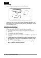
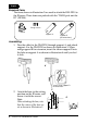
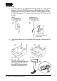
English Required items The items shown in illustration 2 are used to attach the DM-D210 to the IR series. These items are packed with the “DM-D pole unit for IR” (DP-504). 2 fixing screws base support A support B (for extension) Assembling 1. Pass the cable for the DM-D210 through support A, and attach support A to the DM-D210 as shown in illustration 3. When using support B for extension, insert the tab on support B into the hole on support A as shown in illustration 4 until you feel it click.
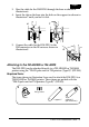
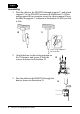
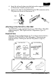
English 3. Pass the cable for the DM-D210 through the base as shown in illustration 6. 4. Insert the tab on the base into the hole on the support as shown in illustration 7 until you feel it click. . 6 7 5. Connect the cable for the DM-D210 to the DM connector on the IR series as shown in illustration 8. 8 Attaching to the TM-H5000II or TM-J8000 The DM-D210 can be attached directly to a TM-H5000II or TM-J8000 printer using the “DM-D pole unit for TM printers (Type B)” (DP-503).
English Assembling 1. Pass the cable for the DM-D210 through support C, and attach support C to the DM-D210 as shown in illustration 10. When using support B for extension, insert the tab on support B into the hole on support C as shown in illustration 11 until you feel it click. 10 11 when using support B for extension 2. Attach the base to the setting position on the TM printer, and secure it with the screws as shown in illustration 12. 3.
English 4. Insert the tab on the base into the hole on the support as shown in illustration 14 until you feel it click. 5. Connect the cable for the DM-D210 to the DM connector on the TM printer as shown in illustration 15. 14 15 Attaching to the TM-U375 or TM-U950 The DM-D210 can be attached directly to a TM-U375 or TM-U950 printer using the “DM-D pole unit for TM printers (Type A)” (DP-502).
English Assembling 1. Pass the cable for the DM-D210 through support C, and attach support C to the DM-D210 as shown in illustration 19. When using support B for extension, insert the tab on support B into the hole on support C as shown in illustration 20 until you feel it click. 19 20 when using support B for extension 2. Attach the rubber feet to the printer as shown in illustration 21 or 22. 21 [TM-U375] 3.
English 4. Connect the cable for the DM-D210 to the DM connector on the TM printer as shown in illustration 24. 24 5. Adjust the length of the cable, and secure fixing plate A to the printer with screws as shown in illustration 25 or 26. 25 26 [TM-U375] [TM-U950] 6. Store any excess cable in the support, and attach the DM-D210 to fixing plate A as shown in illustration 27.
English 28 stopper fixing screws for rubber feet (small) support C fixing screw for stopper angle fixing screw rubber feet (small) support B for extension fixing plate B fixing screws for fixing plate B fixing plate A Assembling 1. Pass the cable for the DM-D210 through support C, and attach support C to the DM-D210 as shown in illustration 29. When using support B for extension, insert the tab on support B into the hole on support C as shown in illustration 30 until you feel it click.
English 2. Attach the rubber feet to the printer as shown in illustration 31. 3. Attach fixing plate B to the printer as shown in illustration 32. 31 32 4. Pass the cable for the DM-D210 through the hole on fixing plate A, and fix the cable at the bottom as shown in illustration 33. 33 5. Connect the cable for the DM-D210 to the DM connector on the TM printer as shown in illustration 34. 6. Attach fixing plate A to the TM printer using the stopper.
English 7. The horizontal rotation mechanism of fixing plate A can be adjusted. To secure the location of the display, set fixing plate A to one of the four positions shown in illustration 36, 37, 38, or 39, and secure it with the angle fixing screw.
English Note: The roll paper cover may not open if the position of the display is not correct. Before securing the position of the display, make sure that you can open the roll paper cover. See illustration 40. 8. Store any excess cable in the support, and attach the DM-D210 to fixing plate A as shown in illustration 41. roll paper cover 40 9. Connect the power cable of the printer. To avoid disconnection, hook the cable to the tabs on fixing plate B, as shown in illustration 42.
English 43 support extension support fixing screws for wooden position fixing plate Velcro tapes (square type) installation manual Velcro tape (round type) Assembling Before assembling this product, you must install the UB-S09 in the TM printer. See the UB-S09 installation manual for the installation instructions. Assembling using Velcro tapes 1. Make sure both the printer and the host computer are turned off. 2. Disconnect the DC cable from the printer.
English 3. Pass the cable for the customer display through the support, and attach the support to the display as shown in illustration 44. When using the extension support, insert the tab on the extension support into the hole on the support as shown in illustration 45 until you feel it click. 44 45 4. Pass the cable for the display through the hole on the fixing plate, and attach the support to the fixing plate as shown in illustration 46. When using an extension support 46 5.
English 3 1 48 47 6 8 5 10 4 2 11 9 7 6. Peel off the backing on the other side of the Velcro tapes, and stick the fixing plate where you want it. 7. Connect the cable for the display to the DC connector on the TM printer (UB-S09) until you feel it click as shown in illustration 49. Store any excess cable in the TM printer, if necessary. 49 TM-T88II printer with the UB-S09 installed. CAUTION: Do not connect this connector to an ordinary telephone line. 8.
English Note: Place the TM-U230 printer as shown in illustration 50. (Do not place it vertically.) 50 9. Connect the power supply to the TM printer. Assembling using screws 1. Follow steps 1 to 4 in “Assembling using Velcro tapes.” 2. Secure the fixing plate where you want it with the fixing screws as shown in illustration 51. 3. Follow steps 7 to 9 in “Assembling using Velcro tapes.
English 52 Velcro tapes Velcro tapes fixing plate A support C support B (for extension) fixing screws for wood position Assembling using Velcro tapes 1. Attach Velcro tapes to the bottom of fixing plate A as shown in illustration 53. 53 2. Pass the cable for the DM-D210 through support C, and attach support C to the DM-D210 as shown in illustration 54. When using support B for extension, insert the tab on support B into the hole on support C as shown in illustration 55 until you feel it click.
English 3. Pass the cable for the DM-D210 through the hole on fixing plate A, and fix the cable at the bottom as shown in illustration 56. 56 4. Connect the cable for the DM-D210 to the DC connector on the TM printer as shown in illustration 57. 57 5. Store any excess cable in the support, and attach the DM-D210 to fixing plate A as shown in illustration 58. 58 6. Peel off the Velcro tapes, and attach the display to the setting position. Assembling using screws 1.
English Attaching to the DM-D Stand The DM-D210 can be attached directly to the DM-D stand using the “DM-D stand unit for DM Customer Display” (DP-210). The DM-D210 with the DM-D stand can be connected to a TM printer or be used as a standalone product. Required items The items shown in illustration 60 or 61 are used to attach the DM-D210 to the DM-D stand. Note that an optional power unit (PS-170) is required when using the DM-D stand.
English Connectors for the DM-D stand The connectors for the DM-D stand are shown in illustration 62. computer connector display connector printer connector 62 power supply unit connector extension cable connector Note: The DM-D stand comes with inch-type hexagonal lock screws installed to secure the interface cable to the interface connector for the RS-232C.
English Precautions on using the power supply unit To avoid damage to the DM-D210 and the power supply unit, note the following points. ❏ Use the optional Seiko Epson products, PS-170, PA-6508, PA-6511, PA-6513, PB-6509, or PB-6510, as the power supply. ❏ Never connect the DC cable to the power supply unit when the power supply unit is connected. ❏ Unplug the DC cable by holding the connector part. If you pull the cable to unplug it, it may be damaged. Assembling 1.
English 3. Connect the cable for the DM-D210 to the display connector on the DM-D stand as shown in illustration 68 until you feel it click. 68 4. Connect one end of the computer interface cable to the computer connector on the DM-D stand; then connect the other end to the RS-232 connector on the computer as shown in illustration 69. Tighten the screws on both ends of the cables to fasten them. 69 5. If using the unit as a standalone, go to step 6.
English 6. If not using the extension cable packed with the DM-D stand for power supply, go to step 7. When using the extension cable, connect it (with the arrow mark up) to the extension cable connector indicated with “POWER OUT” on the DM-D stand; then connect the other end to the power connector on the printer as shown in illustration 71. 71 extension cable connector 7.
English Part Names and Functions Exterior 74 display power switch (bottom of the display) DIP switch (bottom of the display) ❏ Display: Characters are displayed. ❏ Power switch: The power is turned on/off. ❏ DIP switch: The functions of the DM-D210 are changed. See “DIP Switch” for details. Note: When turning on the DM-D210 again after turning it off, wait for at least 3 seconds. DIP Switch DIP Switch Functions The DM-D210 has one group of DIP switches.
English Transmission speed* SW1-5 ON OFF ON OFF ON OFF ON OFF SW1-6 ON ON OFF OFF ON ON OFF OFF SW1-7 ON ON ON ON OFF OFF OFF OFF Transmission speed (bps) 2400 4800 9600 19200 38400 57600 115200 reserve *When the DM-D210 is connected to a TM printer, be sure that the transmission speed matches that of the printer. Setting the DIP switches CAUTION: Turn off the DM-D210 while removing the DIP switch cover to prevent electrical damage to the DM-D210. 1. Turn off the power for the DM-D210. 2.
English With the “DM-D pole unit for IR” (DP-504) and the “DM-D pole unit for TM printers (Type B)” (DP-503), the display area may not face the direction you desire. In this case, remove the base, change the position of the tab on the base so that the display faces in the direction you desire, and reattach it to the base as shown in illustration 76. 330° 76 36° The display area has the following range of movement: ❏ Tilt: 36° max. (3 steps, 4 positions) ❏ Horizontal rotation: 330° max.
English Performing Self Test To perform the self test, follow the steps below. 1. Turn off the power for the DM-D210. 2. Set the SW 1-8 of the DIP switch to ON, and turn on the power. Note: If the contents of the self test are not displayed, the DM-D210 may be malfunctioning. Contact your DM-D210 dealer for assistance. When the self test is finished and no error occurs, the DM-D210 is ready to receive data. Diagnostics The DM-D210 has the diagnostics function.
English Specifications Tilt angle Max 36° (3 steps, 4 positions) Horizontal rotation Max 330° Vacuum fluorescent display • Number of characters: 20 column × 2 lines max. (when using font B) • Display color: Green (505 nm) • Brightness: 700 (cd/m2) Characters Alphanumeric characters: 95, International characters: 37 Extended graphics: 128 × 12 Character grid 5 × 7 dot, comma, period, annunciator Character size 3.5 mm × 5.0 mm {0.138 × 0.199"} Character pitch 9.9 mm {0.
English 260 mm {10.23"} 260mm 503 mm {19.80"} 83 mm {3.27"} 83mm 158 mm {6.22"} 503mm DM-D Stand (DP-210) 158mm 38 mm {1.50"} 38mm 110mm 110 mm {4.33"} 30 DM-D210 Installation Guide 260 mm {10.
English DM-D pole unit for TM printers (Type A) (DP-502) 248 mm {9.76"} 260 mm {10.23"} DM-D pole unit for TM printer (Type B) (DP-503) 129 mm {5.07"} DM-D pole unit for IR (DP-504) 164 mm {6.46"} 78 mm {3.07"} 50 mm {1.97"} 53 mm {2.09"} DM-D pole unit for TM printers (DP-505) 260 mm {10.23"} base 130 mm {5.12"} 214 mm {8.
2001.