English Customer Display DM-D210 Installation Manual/ / 設置マニュアル / 安裝手冊 401285101
CAUTIONS ❏ This document shall apply only to the product(s) identified herein. ❏ No part of this document may be reproduced, stored in a retrieval system, or transmitted in any form or by any means, electronic, mechanical, photocopying, recording, or otherwise, without the prior written permission of Seiko Epson Corporation. ❏ The contents of this document are subject to change without notice. Please contact us for the latest information.
This document presents important information intended to ensure safe and effective use of this product. Please read this document carefully, and store it in an accessible location near your installation. Precaution Headings This document uses the two headings shown below to call attention to potential hazards. Failure to observe the information provided under or alongside these headings may lead to injury or property damage. Be sure that you understand the meaning of each heading before you proceed.
CAUTION: ❏ Do not plug the cable differently from the instruction in this manual. Wrong connection may cause equipment damage and fire. ❏ Be sure to set this equipment on a firm, stable, horizontal surface. Product may be damaged or cause injury if it falls. ❏ Do not use in locations subject to high humidity or dust levels. Excessive humidity and dust may cause equipment damage, fire, or shock. ❏ Do not place heavy objects on top of this product. Equipment may be damaged and cause injury if it falls.
English WARNING You are cautioned that changes or modifications not expressly approved by SEIKO EPSON Corporation could void your authority to operate the equipment. FCC COMPLIANCE STATEMENT FOR AMERICAN USERS This equipment has been tested and found to comply with the limits for a Class A digital device, pursuant to Part 15 of the FCC Rules. These limits are designed to provide reasonable protection against harmful interference when the equipment is operated in a commercial environment.
Contents About This Manual . . . . . . . . . . . . . . . . . . . . . . . . . . . . . . . . . . . . . . . . . . . . . . . . . . . . . . . . 3 Contents . . . . . . . . . . . . . . . . . . . . . . . . . . . . . . . . . . . . . . . . . . . . . . . . . . . . . . . . . . . . . . . . . 4 Unpacking . . . . . . . . . . . . . . . . . . . . . . . . . . . . . . . . . . . . . . . . . . . . . . . . . . . . . . . . . . . . . . . 5 Cautions on Handling . . . . . . . . . . . . . . . . . . . . . . . . . . . . . . . . . . . .
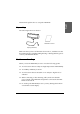
English This manual explains how to set up the DM-D210. Unpacking The following items are in the box. installation manual Display (DM-D210) Make sure that you have all the items shown above, and that none has been damaged. If you find anything missing or damaged items, please contact your DM-D210 dealer. Cautions on Handling When you use the DM-D210, be sure to note the following points: ❏ Avoid locations that are subject to high temperature and humidity. ❏ Avoid dirty and dusty locations.
Usage The DM-D210 can be used with the following equiment. ❏ IR series. You can attach the DM-D210 to the IR series using the “DM-D pole unit for IR” (DP-504). (See page 7.) ❏ TM-H5000II/TM-J8000 printers. You can attach the DM-D210 to TM-H5000II/TM-J8000 printers using the “DM-D pole unit for TM printers (Type B)” (DP-503). (See page 9.) ❏ TM-U375/TM-U950. You can attach the DM-D210 to the TM-U375/ TM-U950 printers using the “DM-D pole unit for TM printers (Type A)” (DP-502). (See page 12.
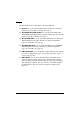
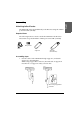
Attaching to the IR series The DM-D210 can be attached directly to the IR series using the “DM-D pole unit for IR” (DP-504). Required items The following items are used to attach the DM-D210 to the IR series. These items are packed with the “DM-D pole unit for IR” (DP-504). fixing screws base support A support B (for extension) Assembling steps 1. Pass the cable for the DM-D210 through support A, and attach support A to the DM-D210.
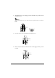
2. Attach the base to the setting position on the IR series, and secure it with the screws. Note: When attaching the base, note that the corners of the base are set as shown below. 3. Pass the cable for the DM-D210 through the base. 4. Insert the tab on the base into the hole on the support until you feel it click. .
English 5. Connect the cable for the DM-D210 to the DM connector on the IR series. Attaching to the TM-H5000II/TM-J8000 The DM-D210 can be attached directly to the TM-H5000II/TM-J8000 printers using the “DM-D pole unit for TM printers (Type B)” (DP-503). Required items The following items are used to attach the DM-D210 to the TM-H5000II/TM-J8000 printers. These items are packed with the “DM-D pole unit for TM printers (Type B)” (DP-503).
Assembling steps 1. Pass the cable for the DM-D210 through support C, and attach support C to the DM-D210. When using support B for extension, insert the tab on support B into the hole on support C until you feel it click. When using support B for extension 2. Attach the base to the setting position on the TM printer and secure it with the screws.
English 3. Pass the cable for the DM-D210 through the base. 4. Insert the tab on the base into the hole on the support until you feel it click. 5. Connect the cable for the DM-D210 to the DM connector on the TM printer.
Attaching to the TM-U375/TM-U950 The DM-D210 can be attached directly to the TM-U375/TM-U950 printers using the “DM-D pole unit for TM printers (Type A)” (DP-502). Required items The following items are used to attach the DM-D210 to the TM-U375/ TM-U950 printers. These items are packed with the “DM-D pole unit for TM printers (Type A)” (DP-502).
English Assembling steps 1. Pass the cable for the DM-D210 through support C, and attach support C to the DM-D210. When using support B for extension, insert the tab on support B into the hole on support C until you feel it click. When using support B for extension 2. Attach the rubber feet to the printer.
3. Pass the cable for the DM-D210 through the hole on fixing plate A, and fix the cable at the bottom as shown below. 4. Connect the cable for the DM-D210 to the DM connector on the TM printer. 5. Adjust the length of the cable and secure fixing plate A to the printer with screws.
English 6. Store any excess cable in the support, and attach the DM-D210 to fixing plate A. Attaching to the TM-H6000/TM-U675 The DM-D210 can be attached directly to the TM-H6000/TM-U675 printers using the “DM-D pole unit for TM printers (Type A)” (DP-502). You can attach fixing plate A on either side of the TM-H6000/TM-U675. After attaching it, you can slide the display freely. Required items The following items are used to attach the DM-D210 to the TM-H6000/ TM-U675 printers.
Assembling steps 1. Pass the cable for the DM-D210 through support C, and attach support C to the DM-D210. When using support B for extension, insert the tab on support B into the hole on support C until you feel it click. When using support B for extension 2. Attach the rubber feet to the printer. 3. Attach fixing plate B to the printer.
5. Connect the cable for the DM-D210 to the DM connector on the TM printer. 6. Attach fixing plate A to the TM printer using the stopper. When you attach the stopper, insert the projections on the stopper into the holes of fixing plate B. Fixing plate A can be attached on either side of the printer. (The illustration below shows fixing plate A attached to the right side of the printer.) 17 English 4.
7. The horizontal rotation mechanism of fixing plate A can be adjusted. To secure the location of the display, set fixing plate A to either one of the following four positions and secure it with the angle fixing screw.
paper roll cover 8. Store any excess cable in the support and attach the DM-D210 to fixing plate A. 9. Connect the power cable of the printer. To avoid disconnection, hook the cable to the tabs on fixing plate B, as shown below. 19 English Note: The paper roll cover may not open if the position of the display is inappropriate. Before securing the position of the display, make sure that you can open the paper roll cover.
Attaching to Other TM Printers When using with other TM printers, the DM-D210 can be attached to a desk or other surface, using the “DM-D pole unit for TM printers (Type A)” (DP-502), and Velcro tapes or screws. Required items The following items are used when the DM-D210 is used with other TM printers. These items are packed with the “DM-D pole unit for TM printers (Type A)” (DP-502).
When using support B for extension 3. Pass the cable for the DM-D210 through the hole on fixing plate A, and fix the cable at the bottom as shown below. 4. Connect the cable for the DM-D210 to the DC connector on the TM printer. 21 English 2. Pass the cable for the DM-D210 through support C, and attach support C to the DM-D210. When using support B for extension, insert the tab on support B into the hole on support C until you feel it click.
5. Store any excess cable in the support, and attach the DM-D210 to fixing plate A. 6. Peel off the Velcro tapes, and attach the display to the setting position. Assembling steps using screws 1. Follow steps 2 and 3 in “Assembling steps using Velcro tapes.” 2. Secure fixing plate A to the setting position with fixing screws. 3. Attach the DM-D210 to fixing plate A.
The DM-D210 can be attached directly to the DM-D stand using the “DM-D stand unit for DM Customer Display ” (DP-210). The DM-D210 with the DM-D stand can be connected to a TM printer, or be used as a stand alone product. Required items The following items are used to attach the DM-D210 to the DM-D stand. Note that an optional power unit (PS-170) is required when using the DM-D stand. If DM-D210 you want to extend the length of the DM-D210. Please get them separately from the DM-D stand unit (DP-501).
Connectors for the DM-D stand The connectors for the DM-D stand are as follows: display connector computer connector power supply unit connector printer connector extension cable connector Note: The DM-D stand comes with inch-type hexagonal lock screws installed to secure the interface cable to the interface connector for RS-232.
English Jumper setting Set the jumpers on the DM-D stand as follows: JP1 JP2 Contents 1-2 1-2 Set the jumpers as in the left columns when connecting both the TM printer and the DM-D stand. (Default setting) 2-3 2-3 Set the jumpers as in the left column when using the DM-D stand as stand alone. (TM printer is not connected.
Assembling steps 1. Pass the cable for the DM-D210 through the DM-D stand. When extending the length of the DM-D stand, attach the extension support to the DM-D stand. When using the extension support 2. 26 Insert the tab on the DM-D210 (or the extension support) into the hole on the DM-D stand until you feel it click.
4. Connect one end of the computer interface cable to the computer connector on the DM-D stand; then connect the other end to the RS-232 connector on the computer. Tighten the screws on both ends of the cables to fasten them. 27 English 3. Connect the cable for the DM-D210 to the display connector on the DM-D stand until you feel it click.
5. When using as a stand alone, go to step 6. When using with the printer, connect one end of the printer interface cable for the printer to the printer connector on the DM-D stand; then connect the other end to the connector on the printer. Tighten the screws on both ends of the cable to fasten them. 6. When not using the extension cable for power supply packed with the DM-D stand, go to step 7.
English 7. Connect the DC cable of the power supply unit (with the arrow mark up) to the power supply unit connector indicated with “POWER IN” on the DM-D stand. DC cable of power supply unit 8. When using as a stand alone product, set the jumpers. (See “Jumper setting” on page 25.) 9. Arrange the cables as shown below. Put the cables for the DM-D210 inside the DM-D stand. 10. When the extension support is used, attach Velcro tapes to the four corners of the plate to avoid falling down. 11.
Part Names and Functions Exterior display power switch (bottom of the display) DIP switch (bottom of the display) ❏ Display: Characters are displayed. ❏ Power switch: The power is turned on/off. ❏ DIP switch: The functions of the DM-D210 are changed. (See “DIP switch” for details.) Note: When turning on the DM-D210 again after turning it off, wait for at least 3 seconds.
English DIP Switch DIP Switch Functions The DM-D210 has one DIP switch. The functions of the DIP switche are as follows: DIP switch 1 DSW1 No. Function ON OFF Default setting 1-1 Data receive error Ignored Displays “?” 1-2 Data length 7 bits 8 bits OFF 1-3 Parity on or off Parity No parity OFF 1-4 Parity type Even Odd OFF OFF 1-5 1-6 ON Change transmission speed See “Transmission speed.
Setting the DIP switches CAUTION: Turn off the DM-D210 while removing the DIP switch cover to prevent electrical damage to the DM-D210. 1. Turn off the power for the DM-D210. 2. Remove the DIP switch cover. DIP switch cover 3. Change each setting of the switches with a pointed object, such as a pen tip or small screwdriver. 4. Close the cover, and turn the power on.
You can turn or tilt the display while holding the support. The display can be moved easily, so do not move any further if it stops. If you move it by force, you may damage it. With the “DM-D pole unit for IR” (DP-504) and the “DM-D pole unit for TM printers (Type B)” (DP-503), the display area maynot face the direction you desire. In this case, remove the base, change the position of the tab ob the base so that the display faces to the direction you desire, and reattach it to the base.
Self Test The DM-D210 has a self test function. If you want to perform a self test, you must change the setting of the DIP switch. Check Items of Self test The following items are checked during the self test: ❏ Control ROM version ❏ DIP switch settings ❏ Memory switch settings ❏ Example of display characters ❏ Example of each function, such as brightness, flashing, and scroll Performing Self test To perform the self test, follow the steps below. 1. Turn off the power for the DM-D210. 2.
English Specification General Specifications ❏ Height, Width, Depth and Weight 260mm 83mm 503mm DM-D Stand (DP-210) 158mm 38mm 110mm 260mm 35
• • DM-D210: Height: Width: Depth: Weight: 91 mm 260 mm 50.
Base and support A of the “DM-D pole unit for IR” (DP-504): Height: 129 mm Width: 50 mm Depth: 53 mm Weight: 60 g • Base and support C of the “DM-D pole unit for TM printers (Type B)” (DP-503): Height: 248 mm Width: 50 mm Depth: 53 mm Weight: 116 g • Fixing plate A and support C of the “DM-D pole unit for TM printers (Type A)” (DP-502): Height: 260 mm Width: 78 mm Depth: 164 mm Weight: 264 g ❏ Tilt angle English • Max 36° (3 steps, 4 positions) ❏ Horizontal rotation Max 330° ❏ Vacuum fluorescent di
Electrical Specifications ❏ Type PS-170, PA-6508, PB-6509, PB-6510, PA-6511, PA-6513 (when using the DM-D stand) ❏ Rated voltage DC 11.4 to 48 V ❏ Rated current 0.4 A (max.
English Character Specifications ❏ Type of character • Alphanumeric characters: 95 • International characters: 37 • Extended graphics: 128 characters × 12 pages ❏ Character grid • Font : 5 × 7 dot, comma, period, annunciator • Character size 3.5 mm x 5.0 mm • Character pitch 9.
❏ 40