DM-D500 Installation Guide 401467400
English All rights reserved. No part of this publication may be reproduced, stored in a retrieval system, or transmitted in any form or by any means, electronic, mechanical, photocopying, recording, or otherwise, without the prior written permission of Seiko Epson Corporation. No patent liability is assumed with respect to the use of the information contained herein.
English Safety Precautions This section presents important information intended to ensure safe and effective use of this product. Read this section carefully, and store it in an accessible location. WARNING: Shut down your equipment immediately if it produces smoke, a strange odor, or unusual noise. Continued use may lead to fire or electric shock. Immediately turn the power off and contact your dealer or a SEIKO EPSON service center for advice. Never attempt to repair this product yourself.
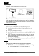
English Unpacking The items shown in illustration 1 are in the box. 1 installation manual warranty card (201 model only) display (DM-D500) Make sure that you have all the items shown, and that none has been damaged. If you find anything missing or damaged, contact your DM-D500 dealer. Cautions on Handling When you use the DM-D500, note the following points: ❏ Avoid locations that are subject to high temperature and humidity. ❏ Avoid dirty and dusty locations.
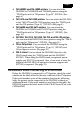
English ❏ TM-H5000II and TM-J8000 printers. You can attach the DM-D500 to TM-H5000II and TM-J8000 printers using the “DM-D pole unit for TM printers (Type B)” (DP-503). (See page 6.) ❏ TM-U375 and TM-U950 printers. You can attach the DM-D500 to the TM-U375 and TM-U950 printers using the “DM-D pole unit for TM printers (Type A)” (DP-502). (See page 8.) ❏ TM-H6000 and TM-U675 printers. You can attach the DM-D500 to TM-H6000 and TM-U675 printers using the “DM-D pole unit for TM printers (Type A)” (DP-502).
English Printer TM-H5000 TM-H5000II Model — 001 011 021 031 041 091 161 181 201 211 Serial No.
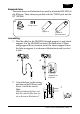
English Required items The items shown in illustration 4 are used to attach the DM-D500 to the IR Series. These items are packed with the “DM-D pole unit for IR” (DP-504). 4 fixing screws base support A support B (for extension) Assembling 1. Pass the cable for the DM-D500 through support A, and attach support A to the DM-D500 as shown in illustration 5. When using support B for extension, insert the tab on support B into the hole on support A as shown in illustration 6 until you feel it click.
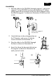
English 3. Pass the cable for the DM-D500 through the base as shown in illustration 8. 4. Insert the tab on the base into the hole on the support as shown in illustration 9 until you feel it click. 5. Connect the cable for the DM-D500 to the DM connector on the IR Series as shown in illustration 10. 8 9 10 Attaching to the TM-H5000II or TM-J8000 The DM-D500 can be attached directly to a TM-H5000II or TM-J8000 printer using the “DM-D pole unit for TM printers (Type B)” (DP-503).
English Assembling 1. Pass the cable for the DM-D500 through support C, and attach support C to the DM-D500 as shown in illustration 12. When using support B for extension, insert the tab on support B into the hole on support C as shown in illustration 13 until you feel it click. 12 13 when using support B for extension 2. Attach the base to the setting position on the TM printer, and secure it with the screws as shown in illustration 14. 14 3.
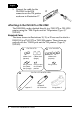
English 5. Connect the cable for the DM-D500 to the DM connector on the TM printer as shown in illustration 17. 17 Attaching to the TM-U375 or TM-U950 The DM-D500 can be attached directly to a TM-U375 or TM-U950 printer using the “DM-D pole unit for TM printers (Type A)” (DP-502). Required items The items shown in illustrations 18, 19, or 20 are used to attach a DM-D500 to a TM-U375 or TM-U950 printer. These items are packed with the “DM-D pole unit for TM printers (Type A)” (DP-502).
English Assembling 1. Pass the cable for the DM-D500 through support C, and attach support C to the DM-D500 as shown in illustration 21. When using support B for extension, insert the tab on support B into the hole on support C as shown in illustration 22 until you feel it click. 21 22 when using support B for extension 2. Attach the rubber feet to the printer as shown in illustration 23 or 24. 23 [TM-U375] 3.
English 4. Connect the cable for the DM-D500 to the DM connector on the TM printer as shown in illustration 26. 26 5. Adjust the length of the cable, and secure fixing plate A to the printer with screws as shown in illustration 27 or 28. 27 28 [TM-U375] [TM-U950] 6. Store any excess cable in the support, and attach the DM-D500 to fixing plate A as shown in illustration 29.
English Required items The items shown in illustration 30 are used to attach the DM-D500 to TM-H6000 or TM-U675 printers. These items are packed with the “DM-D pole unit for TM printers (Type A)” (DP-502). 30 stopper fixing screws for rubber feet (small) fixing screw for stopper angle fixing screw rubber feet (small) support B for extension support C fixing plate B fixing screws for fixing plate B fixing plate A Assembling 1.
English 2. Attach the rubber feet to the printer as shown in illustration 33. 3. Attach fixing plate B to the printer as shown in illustration 34. 33 4. Pass the cable for the DM-D500 through the hole on fixing plate A, and fix the cable at the bottom as shown in illustration 35. 34 35 5. Connect the cable for the DM-D500 to the DM connector on the TM printer as shown in illustration 36. 6. Attach fixing plate A to the TM printer using the stopper.
English 7. The horizontal rotation mechanism of fixing plate A can be adjusted. To secure the location of the display, set fixing plate A to one of the four positions shown in illustration 38, 39, 40, or 41, and secure it with the angle fixing screw.
English Note: The roll paper cover may not open if the position of the display is not correct. Before securing the position of the display, make sure that you can open the roll paper cover. See illustration 42. 8. Store any excess cable in the support, and attach the DM-D500 to fixing plate A as shown in illustration 43. 42 43 roll paper cover 9. Connect the power cable of the printer. To avoid disconnection, hook the cable to the tabs on fixing plate B, as shown in illustration 44.
English Required items The items shown in illustration 45 are used to attach a DM-D500 to a TM-T88II, TM-U210, TM-U230, TM-T90, or TM-L90 printer. These items are packed with the “DM-D pole unit for TM printers” (DP-505). 45 support extension support fixing screws for wooden position fixing plate Velcro tapes (square type) installation manual Velcro tape (round type) Assembling Before assembling this product, you must install the UB-S09 in the TM printer.
English 3. Pass the cable for the customer display through the support, and attach the support to the display as shown in illustration 46. When using the extension support, insert the tab on the extension support into the hole on the support as shown in illustration 47 until you feel it click. 46 4. Pass the cable for the display through the hole on the fixing plate, and attach the support to the fixing plate as shown in illustration 48.
English 5. Peel the backing off of one side of the Velcro tapes, and attach the tapes to both faces of the fixing plate. See the table below to find the attaching position for Velcro tapes and the display for your particular printer. (The positioning numbers of Velcro tapes on the fixing plate are shown in illustrations 49 and 50.
English 8. Place the TM printer on the fixing plate. (See the table below for the mounting position for each TM printer.) Printer type TM-T88II TM-U210/U230/T90/L90 Mounting positions for TM printers Set the printer so that no rubber foot on the rear side of the printer is placed on the Velcro tape. Set the printer so that no rubber foot on the rear side of the printer is placed on the Velcro tape. Set the printer so that the iron plate on the rear side of the printer is placed on the Velcro tapes.
English Required items The items shown in illustration 54 are used when the DM-D500 is used with other TM printers. These items are packed with the “DM-D pole unit for TM printers (Type A)” (DP-502). 54 Velcro tapes Velcro tapes fixing plate A support C support B (for extension) fixing screws for wood position Assembling using Velcro tapes 1. Attach Velcro tapes to the bottom of fixing plate A as shown in illustration 55. 55 2.
English 3. Pass the cable for the DM-D500 through the hole on fixing plate A, and fix the cable at the bottom as shown in illustration 58. 58 4. Connect the cable for the DM-D500 to the DC connector on the TM printer as shown in illustration 59. 59 5. Store any excess cable in the support, and attach the DM-D500 to fixing plate A as shown in illustration 60. 6. Peel off the Velcro tapes, and attach the display to the setting position. 60 Assembling using screws 1.
English Attaching to the DM-D Stand The DM-D500 can be attached directly to the DM-D stand using the “DM-D stand unit for DM-D500” (DP-501). The DM-D500 with the DM-D stand can be connected to a TM printer or be used as a standalone product. Required items The items shown in illustration 62, 63, or 64 are used to attach the DM-D500 to the DM-D stand. Note that an optional power unit (PS-170) is required when using the DM-D stand.
English Connectors for the DM-D stand The connectors for the DM-D stand are shown in illustration 65. computer connector display connector printer connector 65 power supply unit connector extension cable connector Note: The DM-D stand comes with inch-type hexagonal lock screws installed to secure the interface cable to the interface connector for the RS-232C.
English The jumpers are located as shown in illustration 67. 67 Precautions on using the power supply unit To avoid damage to the DM-D500 and the power supply unit, note the following points. ❏ Use the optional Seiko Epson products, PS-170, PA-6508, PA-6511, PA-6513, PB-6509, or PB-6510, as the power supply. ❏ Never connect the DC cable to the power supply unit when the power supply unit is connected. ❏ Unplug the DC cable by holding the connector part.
English 2. Insert the tab on the DM-D500 (or the extension support) into the hole on the DM-D stand as shown in illustration 70 until you feel it click. 70 3. Connect the cable for the DM-D500 to the display connector on the DM-D stand as shown in illustration 71 until you feel it click. 71 4. Connect one end of the computer interface cable to the computer connector on the DM-D stand; then connect the other end to the RS-232C connector on the computer as shown in illustration 72.
English 5. If using the unit as a standalone, go to step 6. When using the DM stand with the printer, connect one end of the printer interface cable for the printer to the printer connector on the DM-D stand; then connect the other end to the connector on the printer as shown in illustration 73. Tighten the screws on both ends of the cable to fasten them. 73 printer 6. If not using the extension cable packed with the DM-D stand for power supply, go to step 7.
English 7. Connect the DC cable of the power supply unit (with the arrow mark up) to the power supply unit connector indicated with “POWER IN” on the DM-D stand as shown in illustration 75. power supply unit connector DC cable of power supply unit 75 8. When using as a standalone product, set the jumpers as shown in “Jumper settings” on page 22. 9. Arrange the cables as shown in illustration 76. Put the cables for the DM-D500 inside the DM-D stand. 10.
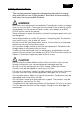
English Part Names and Functions Exterior 78 DIP switch (rear side of the display) display power switch (bottom of the display) ❏ Display: Characters are displayed. ❏ Power switch: The power is turned on/off. ❏ DIP switch: The functions of the DM-D500 are changed. See “DIP Switch” for details. Note: When turning on the DM-D500 again after turning it off, wait for at least 3 seconds.
English DIP Switch DIP Switch Functions The DM-D500 has two groups of DIP switches. The functions of the DIP switches are as follows: DIP switch 1 DSW1 No. 1-1 1-2 1-3 1-4 1-5 1-6 1-7 1-8 Function Data receive error Hand shaking Data length Parity on or off Parity type Change transmission speed ON OFF Ignored Displays “?” XON/XOFF (*1) DTR/DSR 7 bits 8 bits Parity No parity Even Odd See “Transmission speed.
English DIP switch 2 DSW2 No. 2-1 2-2 2-3 2-4 2-5 2-6 2-7 2-8 Function ON OFF Y-connection (*1) Self test selection (*2) 20 column and 2 line mode selection (*3) Device selection default setting Address 0 Address 1 Address 2 Reserved (*5) Enabled Perform self test 20 column and 2 line mode Printer is selected Disabled Do not perform 256 × 64 dots mode Default setting OFF OFF OFF Display is selected OFF The display device number (1-7) corresponds to OFF Address number 0 to 2.
English 2. Remove the DIP switch cover as shown in illustration 79. 79 DIP switch cover 3. Change each setting of the switches with a pointed object, such as a pen tip or small screwdriver. 4. Close the cover, and turn the power on. Turning and Tilting the DM-D500 You can turn or tilt the display while holding the support. The display can be moved easily, so do not move it any further if it stops. If you move it by force, you may damage it.
English Self Test The DM-D500 has a self test function. If you want to perform a self test, you must change the setting of the DIP switch. Check Items of Self Test The following items are checked during the self test: ❏ Control ROM version ❏ DIP switch settings ❏ Example of display characters ❏ Example of each function, such as brightness, flashing, and scroll Performing Self Test To perform the self test, follow the steps below. 1. Turn off the power for the DM-D500. 2.
English Specifications Tilt angle Horizontal rotation Vacuum fluorescent display Characters Character grid Character style Emulation mode Electrical specification Reliability Temperature Humidity Overall dimensions Weight (mass) Max. 48° (4 steps, 5 positions) Max. 90° (for each left and right at 45°) • Total number of dots: 256 × 64 (W × H) • Dot pitch: 0.55 × 0.55 mm {0.0217 × 0.0217"} • Number of characters: 42 column × 8 lines max.
English 213 mm {8.4"} DM-D500 83 mm {3.3"} 65 mm {2.6"} DM-D stand (DP-501) 51 mm {2.0"} 200 mm {7.9"} 48° 118 mm {4.
English DM-D pole unit for IR Series (DP-504) DM-D pole unit for TM printer (Type B) (DP-503) 129 mm {5.0"} DM-D pole unit for TM printers (Type A) (DP-502) 260 mm {10.2"} 248 mm {9.8"} 164 mm {6.5"} 50 mm {1.9"} base 78 mm {3.1"} DM-D pole unit for TM printers (DP-505) 53 mm {2.1"} 130 mm {5.1"} 34 DM-D500 Installation Guide 214 mm {8.4"} 260 mm {10.
2001.