
Drill User Manual


R
F
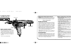
Spade Handle Assembly: (Fig. 1)
This spade handle can be attached either horizontally or vertically.
Place the handle into the locating boss on the back of the drill and
assemble with holding knob.
Side Handle (Fig. 1)
The side handle can be placed in either side of the drill or the top of the
drill according to operator preference and available working clearance.
The spade handle can be temporarily removed if working clearance at
rear of tool is limited. Always replace spade handle when possible.
CAUTION: Always use the side handle and switch handle. This is a
high-torque drill. Always hold it firmly with both hands when operating.
FORWARD
REVERSE
TRIGGER SWITCH
LOCK BUTTON “B”
• OUTDOOR USE EXTENSION CORDS. When tool is used
outdoors, use only extension cords intended for use outdoors
and so marked.
• STAY ALERT. Watch what you are doing. Use common sense.
Do not operate tool when you are tired.
• CHECK DAMAGED PARTS. Before further use of the tool, a
guard or other part that is damaged should be carefully checked
to determine that it will operate properly and perform its intended
function. Check for alignment of moving parts, binding of moving
parts, breakage of parts, mounting, and any other conditions that
may affect its operation. A guard or other part that is damaged
should be properly repaired or replaced by an authorized service
center unless otherwise indicated elsewhere in this instruction
manual. Have defective switches replaced by authorized service
center. Do not use tool if switch does not turn it on and off.
• CAUTION: When drilling or driving into walls, floors or wherever
live electrical wires may be encountered, DO NOT TOUCH ANY
METAL PARTS OF THE TOOL! Hold the tool only by insulated
grasping surfaces to prevent electric shock if you drill or drive into
a live wire.
SAVE THESE INSTRUCTIONS
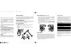
Motor Brushes
Be sure tool is unplugged before inspecting brushes. To inspect brushes,
unscrew the plastic brush inspection caps (located in the sides of the
motor housing) and withdraw the brush assemblies from the tool.
Keep brushes clean and sliding freely in their guides. Carbon brushes
have varying symbols stamped into them, and if the brush is worn down
to a point where the symbol is not visible, they must be replaced. New
brush assemblies are available at Service Centers; see TOOLS,
ELECTRIC in the Yellow Pages.
NOTE: This tool is designed to automatically turn itself off when the
brushes are worn out.
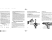
Switch: (Fig. 2)
Pressing the TOP part of the switch runs the tool in a re
Pressing the BOTTOM part of the switch runs the to
direction. Always let the motor stop completely be
direction.
To lock trigger in “FORWARD” position, depress LOWE
and push up lock button “B”. Then, while holding lock bu
gently release trigger. To release locking mechanism,
fully, then release it.
NOTE: Locking mechanism will not function if upper p
depressed (reverse operation).
The locking feature is for use when the drill is mounted in
otherwise firmly held...NOT BY HAND.
Do not lock the switch “ON” when drilling by hand s
instantly release the trigger switch if the bit binds in the h
Be sure to release the switch locking button before dis
plug from the power supply. Failure to do so will cause
immediately the next time it is plugged in. Damage
result.
2 3
FIG. 1
ORK. Use clamps or a vise to hold work. It’s safer
ur hand and it frees both hands to operate tool.
RREACH. Keep proper footing and balance at all
OOLS WITH CARE. Keep tools sharp and clean for
er performance. Follow instructions for lubricating
accessories. Inspect tool cords periodically and if
ve repaired by authorized service facility. Inspect
rds periodically and replace if damaged. Keep
lean, and free from oil and grease.
T OR LOCK OFF TOOLS when not in use, before
when changing accessories, such as blades, bits,
JUSTING KEYS AND WRENCHES. Form habit of
ee that keys and adjusting wrenches are removed
re turning it on.
NTENTIONAL STARTING. Don’t carry tool with
ch. Be sure switch is off when plugging in.
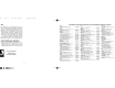
CORDS. Make sure your extension cord is in good
hen using an extension cord, be sure to use one
h to carry the current your product will draw. An
rd will cause a drop in line voltage resulting in loss
overheating. The following table shows the correct
epending on cord length and nameplate ampere
oubt, use the next heavier gage. The smaller the
the heavier the cord.
Minimum Gage for Cord Sets
Total Length of Cord in Feet
0-25 26-50 51-100 101-150
0-50 51-100 101-200 201-300
Rating
Not more AWG
Than
6 18161614
10 18 16 14 12
12 16 16 14 12
16 14 12 Not Recommended
W130 5/17/02 3:26 PM Page 6 (Black plate)