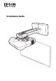
Installation Guide
Safety Instructions For your safety, read all the instructions in this guide before using the mounting bracket. Incorrect handling that ignores instructions in this guide could damage the mounting bracket or could result in personal injury or property damage. Keep this installation guide at hand for future reference. Read the User's Guide and Safety Instructions for your projector and follow the instructions in these documents.
The installation work should be performed by at least two qualified service personnel. If you need to loosen any screws during installation, be careful not to drop the mounting bracket. If the mounting bracket or projector falls, it could cause personal injury or property damage. Inspect the mounting bracket on a regular basis to ensure there are no broken parts or loose screws. If there are any broken parts, stop using the mounting bracket immediately.
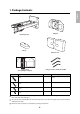
1 Package Contents s Page 5 2 Specifications s Page 6 3 Connecting Devices s Page 7 4 Projection Distance Table s Page 8 5 Installation Procedure (1) (2) (3) (4) (5) s Page 10 Install the wall plate on the wall Determine the projection distance and pull out the slider Attach the mounting bracket to the wall plate Secure the projector to the mounting bracket Connect the power cable and other cables to the projector 6 Adjusting the Projection Screen (1) (2) (3) (4) (5) (6) (7) (8) (9) (10) s P
English 1.
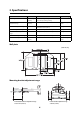
2. Specifications Item Specification Remark Reference Page Mounting bracket mass Approx. 6.3 kg (13.89 lb.) Wall plate (2.2 kg [4.85 lb.]) Covers and cap (0.47 kg [1.04 lb.]) Forward/backward slide adjustment range 0 to 300 mm (11.81 in.) Vertical slide adjustment range ± 4° Minimum: 28 mm (1.10 in.) Maximum: 42.5 mm (1.67 in.) s p. 17 Vertical tilt adjustment range ± 5° Fine adjustments possible with adjustment dial s p.
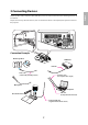
Prepare a power cable, computer cable, USB cable, and so on at the location where the mounting bracket is to be installed. Prepare all necessary cables for devices, such as a document camera or microphone, that you will connect to the projector.
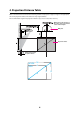
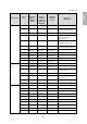
4. Projection Distance Table Refer to the table below and install the mounting bracket and projector to project images at an appropriate size on the projection surface. The values are only rough estimates. The recommended range for the projection distance (a) is 7 to 37 cm (2.76 to 14.57 in.). 65 mm (2.55 in.) Offset value for the position of the center of the screen and the center of the wall plate 240 mm (9.44 in.
Aspect Ratio 4:3 S a b h Screen Size Projection Distance Minimum (Wide) Distance Between Projection Surface and Wall Plate Height of Projection Surface Interactive Whiteboard 63" 71 (2.80) 175 (6.89) 960 (37.80) Hitachi StarBoard FX-63 64" 79 (3.11) 177 (6.97) 975 (38.39) SMART Board 660 Promethean ActivBoard 164 70" 125 (4.92) 191 (7.52) 1067 (42.01) 77" 178 (7.00) 207 (8.15) 1173 (46.18) Hitachi Cambridge Board 77 Hitachi StarBoard FX-77 SMART Board 680 77.5" 182 (7.
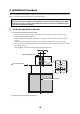
5. Installation Procedure Make sure to follow the steps below to install the mounting bracket. If you ignore these steps, the mounting bracket could fall and cause personal injury or property damage. The maximum combined mass of the mounting bracket and the projector is approximately 15.2 kg (33.5 lb).
The wall plate needs to be secured by commercially available anchors or lag bolts in the following places. It is recommended that the wall plate be secured in at least three places. • If securing the wall plate in four places, make the holes indicated by A or B in the figure. • If securing the wall plate in three places, make the holes indicated by C in the figure. Four mounting holes Three mounting holes (4) Remove the template sheet. (5) Mount the wall plate on the wall.
C Attach the mounting bracket to the wall plate (1) Hang the mounting bracket hook onto the wall plate bar (A). (2) Lift up the mounting bracket and pass the cables through it (B). Caution Take care not to trap the cables between the mounting bracket and wall plate. (3) Tighten the two M8 x 15 mm hexagon socket head cap bolts and two M8 x 35 mm hexagon socket head cap bolts supplied with the mounting bracket so that the mounting bracket becomes horizontal (C).
M5 x 12 mm hexagon socket head cap bolts (2) Side plate Bolt positions Projector interface side Marks (3) Tighten the two M5 x 12 mm hexagon socket head cap bolts (C). Warning If you use adhesives to prevent the screws from loosening or things such as lubricants or oils on the slide plate fixing part of the projector, the case may crack and cause the projector to fall, resulting in personal injury or property damage. Do not use adhesives, lubricants, or oils to install or adjust the mounting bracket.
6. Adjusting the Projection Screen To ensure maximum projection screen quality, follow the steps below to adjust the projection screen. Do not make adjustments with the Keystone function of the projector. Doing so may result in a reduction in image quality. A Turn on the projector Using Remote Control Using Control Panel B Change the aspect ratio Each time you press the [Aspect] button on the remote control, the aspect name is displayed on the screen and the aspect changes.
(1) Move the air filter cover lever to open the air filter cover. (2) Use the focus lever to adjust the focus. Air filter cover Focus lever (3) After you finish making the adjustment, close the air filter cover. E Use the top adjustment dial to adjust the vertical tilt Repeat steps E to I as necessary. (1) Loosen the screw that corresponds to the top adjustment dial (A). (2) Turn the adjustment dial to adjust the vertical tilt (B).
F Use the right adjustment dial to adjust the horizontal rotation (1) Loosen the two screws that correspond to the right adjustment dial (A). (2) Turn the adjustment dial to adjust the horizontal rotation (B). (3) After you finish making all of the adjustments in steps E to I, tighten the two screws you loosened in A. G Use the left adjustment dial to adjust the horizontal roll (1) Loosen the screw that corresponds to the left adjustment dial (A).
Adjust the vertical slide with the two M8 x 35 mm hexagon socket head cap bolts at the bottom of the mounting bracket. Tightening the bolts raises the mounting bracket, and loosening them lowers it. The projection screen is raised or lowered accordingly. M8 x 35 mm hexagon socket head cap bolts (2) I Adjust the forward/backward slide Loosen the four screws and adjust the slider of the mounting bracket. Screws (4) After you finish making all of the adjustments in steps E to I, tighten the screws.
7. Attaching the Covers A Attach the wall plate cover and end cap (1) Secure the wall plate cover with the two M4 x 12 mm hexagon socket head cap bolts (A). q Depending on how the cables are wired, you may need to cut out parts of the wall plate cover to allow the cables to be passed through it. (2) Place the end cap with the concave portion facing up (B).
❏ Never loosen the bolts and nuts after installation. Confirm that the screws have not become loose on a regular basis. If you find any loose screws, tighten them firmly. If the screws are not tightened firmly, the projector or mounting bracket may fall and cause personal injury or property damage. ❏ Do not hang on the mounting bracket or hang a heavy object on the mounting bracket. If the projector or mounting bracket falls, it could cause personal injury or property damage. 8.
English