User’s Guide
Notations Used in This Guide • Safety indications The documentation and the projector use graphical symbols to show how to use the projector safely. Please understand and respect these caution symbols in order to avoid injury to persons or property. Warning This symbol indicates information that, if ignored, could possibly result in personal injury or even death due to incorrect handling.
Contents 3 Notations Used in This Guide . . . . . . . . . . . . . . . . . . . . . . . . 2 Switch to the Target Image by Remote Control . . . . . . . . . . . . . . . . . . . . . . . . . 26 Changing the Aspect Ratio of the Projected Image . . . . . . . . . . . . 27 Changing the Aspect Mode . . . . . . . . . . . . . . . . . . . . . . . . . . . . . . . . . . . . . . . 27 Projecting images from video equipment or from the HDMI input port . . . . . . . 27 Projecting images from a computer . . . . . . . . . .
Contents Managing Users (Password Protect) . . . . . . . . . . . . . . . . . . . . . . . . . Type of Password Protect . . . . . . . . . . . . . . . . . . . . . . . . . . . . . . Setting Password Protect . . . . . . . . . . . . . . . . . . . . . . . . . . . . . . Entering the Password . . . . . . . . . . . . . . . . . . . . . . . . . . . . . . . . Restricting Operation (Control Panel Lock) . . . . . . . . . . . . . . . . . . . . Anti-Theft Lock . . . . . . . . . . . . . . . . . . . . . . . . . . . . . . . .
Contents 5 When Transporting . . . . . . . . . . . . . . . . . . . . . . . . . . . . . . . . . . . . . . . . . . . 102 Preparing packaging . . . . . . . . . . . . . . . . . . . . . . . . . . . . . . . . . . . . . . . . 102 Notes when packing and transporting . . . . . . . . . . . . . . . . . . . . . . . . . . . . 102 Making a connection using the push button method . . . . . . . . . . . . . . . . . . 119 Making a connection using the PIN Code Method . . . . . . . . . . . . . . . . . . . . .
Contents 6 Screen Size and Projection Distance . . . . . . . . . . . . . . . . . . . . . . . . 141 Projection Distance . . . . . . . . . . . . . . . . . . . . . . . . . . . . . . . . . . . . . . . . . . . 141 Supported Monitor Displays . . . . . . . . . . . . . . . . . . . . . . . . . . . . . . . 143 Supported Monitor Displays . . . . . . . . . . . . . . . . . . . . . . . . . . . . . . . . . . . . . Computer signals (analog RGB) . . . . . . . . . . . . . . . . . . . . . . . . . . . . . . . . .
Introduction This chapter explains the projector's features and the part names.
Projector Features Ease of Use when Installed on a Ceiling Mount 8 Meets a Wide Range of Needs Centered lens Equipped with a high-resolution WUXGA panel The lens is positioned in the center of the projector so it is well balanced and is easy to mount on a ceiling. This also makes it easy to line up the screen and the projector. You can project a dramatic amount of information on the screen. Viewers can see the information at a glance without having to scroll or switch screens.
Projector Features As well as Color Mode, you can also adjust the image's absolute color temperature and the strength of each RGB color. Also, because you can adjust the hue, saturation, and brightness of each RGBCMY, the image can be projected with depth and a color matching in superior detail. 9 Monitoring and Control Functions A selection of monitoring and control protocols is supported, such as the Epson EasyMP Monitor application software.
Part Names and Functions 10 Front/Top Name Function C Front adjustable foot Extend and adjust the position of the projected image when the projector is placed on a surface such as a desk. s Quick Start Guide D Foot adjust lever Pull out the foot lever to extend and retract the front foot. s Quick Start Guide E Zoom ring Adjusts the image size. s Quick Start Guide F Projection lens Images are projected through here.
Part Names and Functions 11 Name Base Function E Security cable installation point Pass a commercially available anti-theft wire lock through here when you want to secure the projector to a fixed object. s p.48 F Handle Use these handles when carrying the projector. G Screw hole for the screw to fix the lens unit removal button When installing a lens unit, use this screw hole to fix the lens unit removal button using the screw supplied. s p.
Part Names and Functions 12 Name Interface Name Function A Monitor Out port Outputs to an external monitor the analog RGB signal from the computer connected to the Computer1 input port or BNC input port. The signals that are input from other ports and component video signals cannot be output. B Audio Out port Outputs the sound of the image currently being projected to external speakers. C Audio3 input port Connects to the audio out port of the device that is connected to the BNC input port.
Part Names and Functions Name 13 Function Q DVI-D input port Inputs digital RGB signals from a computer connected to the DVI-D ouput port. This projector is compatible with HDCPg signals. R Audio2 input port Connects to the audio out port of the device that is connected to the DVI-D input port. Turns the projector power On or Off. s Quick Start Guide B [Source Search] button Changes to the next input source that is connected to the projector and is sending an image. s p.
Part Names and Functions Remote Control 14 Name Function A [t] button Turns the projector power On or Off. s Quick Start Guide B [Comp1/2] button Changes to images from the Computer1 input port. C [BNC] button Changes to images from the BNC input port. D [Video1/2] button Each time the button is pressed, the image displayed changes between Video1 input port and Video2 input port. E [S-Video] button Changes to images from the S-video input port.
Part Names and Functions Name 15 Function Name M [Aspect] button The Aspect Ratiog changes each time the button is pressed. s p.27 N [ID] button Press to set the remote control ID. s p.39 O [Help] button Displays and closes the Help screen which shows you how to deal with problems if they occur. s p.78 P Remote port Connects the optional remote control cable set and outputs signals from the remote control.
Part Names and Functions Attention Make sure you read the Safety Instructions before handling the batteries. s Safety Instructions Procedure A Remove the battery cover. 16 Caution Check the positions of the (+) and (-) marks inside the battery holder to ensure the batteries are inserted the correct way. C Replace the battery cover. Press the battery compartment cover until it clicks into place. While pushing the battery compartment cover catch, lift the cover up.
Part Names and Functions Operating range of remote control When using the remote control, point the remote control light-emitting area at the remote receiver on the projector. The operating range of the remote control that is provided with the projector is shown below. Horizontal operating range Vertical operating range q • To restrict reception of the operation signals from the remote control, set the Remote Receiver on the Set menu. s p.
Useful Functions This chapter explains useful tips for giving presentations, and the security functions.
Adjusting the Projected Image B Press the [h] button on the remote control in the [r] direction Displaying a Test Pattern A test pattern can be displayed to adjust the projection status without connecting video equipment. This is useful when installing a projector. q 19 If the [User] button on the remote control is set to Test Pattern, the test pattern will be displayed when the [User] button is pressed. (The default setting is Test Pattern.
Adjusting the Projected Image q To set menu items that cannot be set while the test pattern is being displayed or to fine-tune the projected image, project an image from the connected device. C Press the [Esc] button to end the test pattern. 20 q The image will be clearest when both the vertical and horizontal lens shift dials are set in the center. The ranges within which the image can be moved using the lens shift dials are shown below.
Adjusting the Projected Image • H/V-Keystone This allows you to manually correct distortion in the horizontal and vertical directions independently. You can perform easy H/V-Keystone corrections by using the [w/ ], [v/ ], [/ ] buttons on the projector's control panel. s "H/V-Keystone" p.23 Quick Corner and horizontal and vertical keystone cannot be performed at the same time.
Adjusting the Projected Image 22 D Correct the position of the corner using the [h] button on the remote control, or the [w/ ], [v/ buttons on the control panel. ], [/ ] If the triangle in the direction you are adjusting the shape turns gray, as shown in the screenshot below, you cannot adjust the shape any further in that direction.
Adjusting the Projected Image F When you are done, press the [Esc] button to exit the correction menu. Because the correction method was changed to Quick Corner from Keystone in the configuration menu, when [w/ ], [v/ ], [/ ] buttons are pressed later, the screen for selecting the corner in procedure 2 is displayed. Change Keystone from the configuration menu to H/V-Keystone if you want to correct H/VKeystone when pressing the [w/ ], [v/ ], [/ ] buttons on the control panel. s p.
Adjusting the Projected Image • Correcting horizontal keystone Horizontal keystone can be corrected to a horizontal projector tilt of up to 20˚. 24 q Shift the lens to the position shown below when performing horizontal and vertical keystone. When the lens shift is not positioned as below, the distortion is not corrected accurately. s "Adjusting the Position of the Projected Image (Lens Shift)" p.20 • The horizontal lens shift is set to the center. • The vertical lens shift is set to the top or bottom.
Changing the Projected Image You can change the projected image in the following two ways. • Changing by Source Search The projector automatically detects signals being input from connected equipment, and the image being input from the input port is projected. 25 When the [Source Search] button is pressed, a search is made for input ports to which video signals are being input in the following order. (The input port where no image signal is being input is skipped.
Changing the Projected Image q The following screen showing the status of image signals remains displayed when only the image that the projector is currently displaying is available, or when no image signal can be found. You can select the input port where the equipment you want to use is connected. If no operation is performed after about 10 seconds, the screen closes.
Changing the Aspect Ratio of the Projected Image You can select the aspect mode according to the type of input signal, ratio of height and width, and resolution to switch the Aspect Ratiog of the projected image. The aspect modes are listed below. The aspect modes that can be set depend on the type of image that is being projected. Aspect mode Explanation Normal Projects to the full projection size retaining the aspect ratio of the input image.
Changing the Aspect Ratio of the Projected Image C Full D Zoom E Native 28 Aspect mode Input Signal XGA 1024X768(4:3) WXGA 1280X800(16:10) SXGA 1280X1024(5:4) Native Projecting images from a computer Each time the [Aspect] button on the remote control is pressed, the aspect mode changes in the order Normal, 16:9, Full, Zoom, and Native. s p.27 Projection examples for each aspect mode are shown below.
Selecting the Projection Quality (Selecting Color Mode) You can easily obtain the optimum image quality simply by selecting the setting that best corresponds to your surroundings when projecting. The brightness of the image varies depending on the mode selected. Mode 29 Procedure Remote Control Application Dynamic Ideal for use in a bright room. This is the brightest mode. Presentation Ideal for making presentations using color materials in a bright room.
Projecting Two Images Simultaneously (Split Screen) A split screen can be used to divide the screen into a left screen (U) and a right screen (V) and simultaneously project two images. 30 Operating Procedures Projecting on a split screen Procedure A Press the [Split] button on the remote control while the projector is projecting. The currently selected input source will be displayed on the left screen.
Projecting Two Images Simultaneously (Split Screen) q The Split Screen Setup will also be displayed when the [Source Search] button is pressed on the remote control or control panel or when a Source button is pressed on the remote control. 31 B Select "Swap Screens" and then press the [Enter] button. The images on the left and right screens will be swapped. C To switch the image projected on the left screen, select "Source Left" and press the [Enter] button.
Projecting Two Images Simultaneously (Split Screen) The projected images will appear as shown below after setting the screen size. Equal Larger Left 32 Ending the split screen Procedure To end the split screen, press the [Esc] button on the remote control or control panel. The following steps can also be used to end the split screen. • Press the [Split] button on the remote control. • Select Exit Split Screen in the Split Screen Setup and then press the [Enter] button.
Projecting Two Images Simultaneously (Split Screen) Restriction relating to images • The default values for the Image menu are applied to the image on the right screen. However, the settings for the image projected on the left screen are applied to the image on the right screen for the Color Mode, Abs. Color Temp., and Color Adjustment. Also, the Advanced settings for Sharpness (Thin Line Enhancement, Thick Line Enhancement) are ignored for the images on both screens. s p.
Functions for Enhancing Projection Hiding the Image and Sound Temporarily (A/V Mute) You can use this when you want to focus the audience's attention on what you are saying, or if you do not want to show details such as when you are changing between files during presentations from a computer. 34 q • If you use this function when projecting moving images, the images and sound continue to be played back by the source, and you cannot return to the point where A/V Mute was activated.
Functions for Enhancing Projection q • Audio does not stop. • The image source continues to play back the moving images even while Freeze is on, and so it is not possible to resume projection from the point where it was paused. • If the [Freeze] button is pressed while the configuration menu or a Help screen is displayed, the menu or Help screen being displayed is cleared. • Freeze still works while E-Zoom is being used. 35 Procedure A Display the Pointer.
Functions for Enhancing Projection B Move the Pointer icon ( 36 Procedure ). A Start E-Zoom. Remote Control Remote Control q You can choose from three different kinds of Pointer icon ( or , , ) in Settings - Pointer Shape from the configuration menu. s p.55 B Move the ( ) to the area of the image that you want to enlarge. Remote Control Enlarging Part of the Image (E-Zoom) This is useful when you want to expand images to see them in greater detail, such as graphs and tables.
Functions for Enhancing Projection C Enlarge. Remote Control Each time the button is pressed, the area is expanded. You can expand quickly by holding the button down. You can reduce the enlarged image by pressing the [x] button. Press the [Esc] button to cancel. q • The enlargement ratio appears on the screen. The selected area can be enlarged to between 1 to 4 times in 25 incremental steps. • After the image is enlarged, it can be scrolled with the [h] button.
Limitation of the Number of the Target Projectors when Using Multiple Projectors 38 When an ID is set for the projector and the remote control, you can use the remote control to operate only the projector with a matching ID. This is very useful when managing multiple projectors. When operating all of the projectors from the remote control, set the ID switch on the side of the remote control to Off.
Limitation of the Number of the Target Projectors when Using Multiple Projectors Procedure 39 Setting the Remote Control ID A Set the remote control ID switch to On. Procedure A Set the remote control ID switch to On. B During projection, while holding the [ID] button, press the [Help] button. Remote Control B While holding the [ID] button, press a number button to select a number to match the ID of the projector you want to operate. s "Checking the Projector ID" p.
Limitation of the Number of the Target Projectors when Using Multiple Projectors q The remote control ID setting is saved in the remote control. Even if the remote control batteries are removed to replace them and so on, the stored ID setting is retained. However, if the batteries are left out for a long time, it is reset to the default value (ID0).
Color Correction when Projecting from Multiple Projectors (Multi-screen Color Adjustment) When multiple projectors are lined up and projecting images, you can manually correct the brightness and color tone of each projector's image so that the colors projected from each projector match closely. Use the multi-screen color adjustment function when the Color Mode of each projector is set to the same item. In some cases the brightness and color tone may not match completely even after correction.
Color Correction when Projecting from Multiple Projectors (Multi-screen Color Adjustment) • Each time a level is selected, the pattern of the level selected is displayed. • You can start correcting from any level, usually you can make it darker or lighter by correcting 1 to 5 or 5 to 1. C Correct the brightness with "Brightness Correct.". • When you select Lv. 5, all the images are adjusted to the darkest image from multiple projectors. • When you select Lv.
Saving a User's Logo 43 You can save the image that is currently being projected as a User's Logo. The saved user's logo can be used as the display image when there is no video signal input or during the A/V Mute operation. q Once a User's Logo has been saved, the logo cannot be returned to the factory default. Procedure A Project the image you want to use as the user's logo, and then press the [Menu] button.
Saving a User's Logo 44 D Move the box to select the part of the image to use as the User's Logo. q You can save at up to 400 ^ 300 dots in size. E When "Select this image?" is displayed, select "Yes". F Select the zoom factor from the zoom setting screen. Using the Remote Control Using the Control panel G When the message "Save this image as the User's Logo?" is displayed, select "Yes". The image is saved. After the image has been saved, the message "Completed." is displayed.
Security Functions The projector has the following enhanced security functions. • Password Protect You can limit who can use the projector. • Control Panel Lock You can prevent people changing the settings on the projector without permission. s p.47 • Anti-Theft Lock The projector is equipped with various types of anti-theft security devices. s p.
Security Functions q 46 Remote Control • If Password Protect is already activated, you must enter the Password. If the Password is entered correctly, the Password Protect setting menu is displayed. s "Entering the Password" p.46 • When the Password is set, stick the Password protect sticker in a visible position on the projector as a further theft deterrent. B Turn on "Power On Protect". (1) (2) (3) Select Power On Protect, and then press the [Enter] button.
Security Functions Attention • If an incorrect password is entered three times in succession, the message "The projector's operation will be locked." is displayed for about five minutes, and then the projector switches to standby mode. If this happens, disconnect the power plug from the electrical outlet and then reinsert it and turn the projector's power back on. The projector displays the Password entry screen again so that you can enter the correct Password.
Security Functions q 48 You can release the control panel lock by one of the following two methods. • From the remote control, select Off in Settings - Control Panel Lock from the configuration menu. s p.55 • Hold down the [Enter] button on the Control panel for about seven seconds, a message is displayed and the lock is released.
Configuration Menu This chapter explains how to use the configuration menu and its functions.
Using the Configuration Menu Selecting from the top menu 50 Selecting from the sub menu Setting Each Item Exit
Image Menu 51 Items that can be set vary depending on the image signal or input source currently being projected as shown in the following screen shots. Setting details are saved for each image signal. Component Video Signal g/ Composite video Signal g/S-Video Signal g RGB Signal/USB/LAN Sub Menu Function Color Mode You can select the quality of the image to suit your surroundings. s p.29 Brightness You can adjust the image Brightness.
Image Menu 52 Sub Menu Function Color Adjustment You can make adjustments by choosing one of the following. Red, Green, Blue*4: You can adjust the saturation of each color individually. R, G, B, C, M, Y: You can adjust the hue, saturation, and brightness of each color R (red), G (green), B (blue), C (cyan), M (magenta), Y (yellow) individually. (This item can be set simply by setting the Color Mode to Customized.
Signal Menu 53 Items that can be set vary depending on the image signal or input source currently being projected as shown in the following screen shots. Setting details are saved for each image signal. You cannot make settings in the Signal menu when the input source is USB or LAN.
Signal Menu 54 Sub Menu Function DVI/HDMI Video Range When the DVI-D or the HDMI input port are connected to a DVD player, set the video level according to the video level setting of the DVD player. When HDMI is selected for the input source and the range is set to Auto*3, the video level of the input signal will be automatically determined. If the range is set to Auto and the image shows whiteout or blackout, set the video level according to the video level setting of the DVD player.
Settings Menu 55 Sub Menu Keystone Function You can correct keystone distortion. H/V-Keystone: Corrects horizontal and vertical keystone distortion. Select one of V-Keystone or H-Keystone. s p.23 Use the [w/ ], [v/ ], [/ ] buttons on the control panel to perform similar corrections to V-Keystone and H-Keystone. Quick Corner: Selects and corrects the four corners of the projected image. s p.21 Split Screen You can split the screen into two screens. s p.
Settings Menu Sub Menu 56 Function User Button You can select the item assigned from the configuration menu with the remote control's [User] button. By pressing the [User] button the assigned menu item selection/adjustment screen is displayed, allowing you to make one-touch settings/adjustments. You can assign one of the following six items to the [User] button.
Extended Menu Sub Menu 57 Function Display You can make settings related to the projector's display. Messages: The following messages are not displayed on the screen when this item is set to Off. Overheating and other warnings, messages such as when there is no video input, and when Freeze is On or when changing Source, Color Mode or Aspect. Display Background*1: You can set the screen status for when no image signal is available to Black, Blue, or Logo.
Extended Menu 58 Sub Menu Function Operation Direct Power On: You can set whether or not (On/Off) to enable Direct Power On. Be careful when this item is set to On because this unit turns on at the time of power recovery with this unit plugged-in to an outlet. Sleep Mode: When set to On, this automatically stops projection when no image signal is being input and no operations are carried out.
Extended Menu 59 Sub Menu Reset Function Display*2, Operation*3, You can reset and Air Filter Notice from the Extended menu to their default settings. To return all menu items to their default settings, see s p.76 *1 When User's Logo Protect is set to On in Password Protect, settings relating to the user's logo cannot be changed. You can make changes after setting User's Logo Protect to Off. s p.43 *2 Except for parameters related to the user's logo.
Network Menu 60 When Network Protect is set to On in Password Protect, a message is displayed and the settings cannot be changed. You can make changes after setting Network Protect to Off. s p.45 Sub Menu Function Net. Info. - Wireless LAN Net. Info. - Wired LAN Displays the network settings. Network Configuration Displays the screen to set the network. s p.
Network Menu 61 Notes on Operating the Network Menu Selecting from the top menu and sub menus, and changing of selected items are the same as operations in the configuration menu. When done, make sure you go to the Setup complete, and select one of Yes, No, or Cancel. When you select Yes or No, you return to the configuration menu. Yes: No: Cancel: Saves the settings and exits the Network menu. Exits to the Network menu without saving the settings. Continues displaying the Network menu.
Network Menu 62 Basic Menu Sub Menu Function Projector Name Displays the projector name used to identify the projector when connected to a network. When editing, you can enter up to 16 single-byte alphanumeric characters. PJLink Password Set a password to use when you access the projector using compatible PJLink software. s p.111 You can enter up to 32 single-byte alphanumeric characters.
Network Menu 63 Wireless LAN Menu To connect the projector to a computer using a wireless LAN, install the Wireless LAN unit (ELPAP03). s p.134 Sub Menu Function Wireless LAN Power Set this parameter to On when connecting the projector and a computer via a wireless LAN. If you do not want to connect via a wireless LAN, set this parameter to Off to prevent unauthorized access by others. Connection Mode Set the connection mode to use when connecting the projector and a computer via a wireless LAN.
Network Menu 64 Sub Menu Function DHCP You can set whether or not (On/Off) to use DHCPg. If this is set to On you cannot set any more addresses. IP Address You can input the IP addressg assigned to the projector. You can input a number from 0 to 255 in each field of the address. However, the following IP addresses cannot be used. 0.0.0.0, 127.x.x.x, 224.0.0.0 to 255.255.255.255 (where x is a number from 0 to 255) Subnet Mask You can input the Subnet Maskg for the projector.
Network Menu 65 Security Menu (Only available when the Wireless LAN unit is installed) When the Wireless LAN unit is installed and being used in Advanced mode, it is strongly recommended that you set security. Sub Menu Security q Function You can select one type of security. When setting up security, follow the instructions from the administrator of the network system you are about to access. The following types of security are provided by the projector.
Network Menu 66 When WEP is selected Sub Menu Function WEP Encryption You can set the encryption for WEP encoding. 128 Bit: Uses 128 (104) bit encoding 64 Bit: Uses 64 (40) bit encoding Format You can set the input method for the WEP encrypted key. ASCII: Input text. The method of inputting the encrypted WEP with text differs depending on the access point. Check with the network administrator for the network in which the projector participates, and then set to "ASCII". HEX: Input in hexadecimal.
Network Menu 67 Sub Menu Authentication Type Function You can set Authentication Type for WEP encoding. Open: Method to connect access point with no authentication. Shared: Authentication Type using WEP key.
Network Menu 68 When WPA-PSK(TKIP/AES) or WPA2-PSK(TKIP/AES) is selected Sub Menu PSK (Encryption key) Function You can enter a Pre-Shared Key (encrypted key) in single-byte alphanumeric characters. Enter at least 8 and up to 63 characters. When the Pre-Shared Key is entered and the [Enter] button is pressed, the value is set and displayed as an asterisk (*). You cannot enter more than 32 characters on the configuration menu. When setting from Web Control, you can enter more than 32 characters. s p.
Network Menu 69 When EAP-TLS is selected Refer to the following information to register a digital certificate to the projector for authentication. s PC Free Operation Guide "Registering a Digital Certificate to the Projector" Sub Menu Issued to/Issued by/Validity period Function Information in the certificate is displayed. You cannot enter.
Network Menu 70 EAP-TTLS/MD5, EAP-TTLS/MS-CHAPv2, PEAP/MS-CHAPv2, PEAP/GTC, LEAP, EAP-Fast/MS-CHAPv2, EAP-Fast/GTC is selected Sub Menu Function User name You can enter a user name to be used for authentication in single-byte alphanumeric characters (no spaces). You can enter up to 64 characters. You cannot enter more than 32 characters on the configuration menu. When setting from Web Control, you can enter more than 32 characters. s p.
Network Menu 71 Wired LAN Menu Sub Menu Function DHCP You can set whether or not (On/Off) to use DHCPg. If this is set to On you cannot set any more addresses. IP Address You can input the IP addressg assigned to the projector. You can input a number from 0 to 255 in each field of the address. However, the following IP addresses cannot be used. 0.0.0.0, 127.x.x.x, 224.0.0.0 to 255.255.255.255 (where x is a number from 0 to 255) Subnet Mask You can input the Subnet Maskg for the projector.
Network Menu 72 Mail Menu When this is set, you receive an e-mail notification if a problem or warning occurs in the projector. s "Reading Problem Mail Notification Function" p.107 Sub Menu Function Mail Notification You can set whether or not (On/Off) to be notified by e-mail. SMTP Server You can input the IP addressg for the SMTP server for the projector. You can input a number from 0 to 255 in each field of the address. However, the following IP addresses cannot be used. 127.x.x.x, 224.0.0.
Network Menu 73 Others Menu Sub Menu Function SNMP Set this parameter to On when using SNMPg to monitor the projector. To use SNMP to monitor the projector, you need to install the SNMP manager program on your computer. SNMP should be managed by a network administrator. Trap IP Address 1/Trap IP Address 2 When SNMP is set to On, you can set up to two IP addresses as SNMP trap notification destinations. You can input a number from 0 to 255 in each field of the address.
Network Menu 74 Reset Menu Resets all of the network settings. Sub Menu Reset network settings. Function To reset all of the network settings, select Yes. After you reset all the settings, the Basic menu appears.
Info Menu (Display Only) 75 Lets you check the status of the image signals being projected and the status of the projector. Items that can be displayed vary depending on the image signal or input source being projected as shown in the following screen shots. RGB Signal/Component Videog Signal Composite videog Signal/S-Videog Signal Sub Menu USB/LAN Function time*1. Lamp Hours You can display the cumulative lamp operating When it reaches the lamp warning time, the characters are displayed in yellow.
Reset Menu Sub Menu 76 Function Reset All You can reset all items in the configuration menu to their default settings. The following items are not reset to their defaults: Items for Password, Input Signal, User's Logo, Multi-screen, all items for Network menus, Lamp Hours, and Language. Reset Lamp Hours You can clear the cumulative lamp hours use time, and return it to "0H". Reset when you replace the lamp.
Troubleshooting This chapter explains how to identify problems and what to do if a problem is found.
Using the Help 78 If a problem occurs with the projector, the Help screen is displayed to assist you by pressing the [Help] button. You can solve problems by answering the questions. Procedure A Press the [Help] button. Using the Remote Control The Help screen is displayed. Using the Remote Control B Select a menu item.
Using the Help 79 C Confirm the selection. Using the Remote Control Using the Control panel Questions and solutions are displayed as shown on the screen below. Press the [Help] button to exit Help. q If the Help screen does not provide a solution to the problem, refer to "Problem Solving" p.80.
Problem Solving 80 If you are having a problem with the projector, first check the projector's indicators and refer to "Reading the Indicators" below. If the indicators do not show clearly what the problem might be, refer to "When the Indicators Provide No Help". s p.84 Reading the Indicators These indicators indicate the operating status of the projector. A Indicates the operating status. Standby condition When the [t] button is pressed in this condition, projection starts.
Problem Solving 81 C Indicates the internal temperature status. D Indicates the projection lamp status. Refer to the following table to see what the indicators mean and how to remedy problems that they indicate. If all indicators are off, check that the power cable is connected correctly and that the power is being supplied normally. Sometimes, when the power cable is unplugged, the t indicator remains lit for a short period, but this is not a fault.
Problem Solving 82 Status Cause Lamp Error Lamp Failure Lamp Cover Open Remedy or Status Check the following two points. • Take out the lamp and check whether it is cracked. s p.97 • Clean the air filter. s p.94 If it is not cracked: Re-fit the lamp and turn on the power. If the error continues: Replace the lamp with a new lamp and turn on the power.
Problem Solving Status q 83 Cause Remedy or Status Low Air Flow (This is not an abnormality. However, projection stops automatically if the airflow falls any further.) The message "The air filter is clogged. Clean or replace the air filter. " is displayed. Check the following two points. • Check that the air filter and air exhaust vent are clear, and that the projector is not positioned against a wall. • If the air filter is clogged, clean or replace it. s p.94, p.
Problem Solving When the Indicators Provide No Help If any of the following problems occur and the indicators do not offer a solution, refer to the pages given for each problem. Problems relating to images • "No images appear" s p.85 Projection does not start, the projection area is completely black, the projection area is completely blue, and so on. • "Moving images are not displayed (only the moving image portion turns black)." s p.
Problem Solving 85 Problems relating to images No images appear Check Remedy Did you press the [t] button? Press the [t] button to turn the power on. Are the indicators switched off? The power cable is not connected correctly or power is not being supplied normally. Connect the projector's power cable correctly. s Quick Start Guide Check that your electrical outlet or power source is functioning correctly. Is A/V Mute active? Press the [A/V Mute] button on the remote control to cancel A/V Mute.
Problem Solving 86 The message "Not supported" is displayed. Check Is the image signal format setting correct? Remedy Change the setting according to the signal for the connected equipment. s Signal Menu - Video Signal p.53 Only when projecting images from a video source Do the image signal Resolution and the Refresh Rate correspond to Refer to the computer's documentation for how to change the image signal Resolution and the Refresh Rate output from the computer. s "Supported Monitor Displays" p.
Problem Solving 87 Check Has condensation formed on the lens? Remedy If the projector is suddenly taken from a cold environment to a warm environment, or if sudden ambient temperature changes occur, condensation may form on the surface of the lens, and this may cause the images to appear fuzzy. Set the projector up in the room about one hour before it is used. If condensation forms on the lens, turn the projector off and wait for the condensation to disappear.
Problem Solving 88 Check Remedy Is Position adjusted correctly? Press the [Auto] button on the remote control or the [Enter] button on the control panel to perform automatic adjustment when projecting the computer analog RGB signals. If the images are not adjusted correctly after using automatic adjustment, you can make the adjustments using Position from the configuration menu.
Problem Solving 89 Check Is the lamp due for replacement? Remedy When the lamp is nearly ready for replacement, the images become darker and the color quality becomes poorer. When this happens, replace the lamp with a new lamp. s p.97 Problems when projection starts No power supplied Check Remedy Did you press the [t] button? Press the [t] button to turn the power on. Are the indicators switched off? The power cable is not connected correctly or power is not being supplied normally.
Problem Solving 90 Other problems No sound can be heard or the sound is faint Check Remedy Is the audio source connected correctly? Disconnect the cable from the audio input port, and then reconnect the cable. Is the volume adjusted to the minimum setting? Adjust the volume so that sound can be heard. s Quick Start Guide Is A/V Mute active? Press the [A/V Mute] button on the remote control to cancel A/V Mute. s p.
Problem Solving 91 Nothing appears on the external monitor Check Remedy Are you trying to display an image from an input port other Only RGB signals from the Computer1 input port or the BNC input port can be displayed on an external than the Computer1 input port or the BNC input port? monitor. Are you projecting a split screen? Only RGB signals projected on the left screen from the Computer1 input port or the BNC input port can be displayed on an external monitor. s p.
Problem Solving 92 Interpreting Event IDs Check the event ID and perform the remedy given below. If the problem cannot be solved, contact the network administrator or one of the following contact addresses. s Epson Projector Contact List Event ID Cause Remedy 0432 0435 Failed to startup EasyMP Network Projection. Restart the projector. 0434 0481 0482 0485 Network communication is unstable. Check the status of network communications. Wait for a while and then try connecting again.
Maintenance This chapter explains the maintenance methods that are required to ensure a long projector service life.
Cleaning You should clean the projector if it becomes dirty or if the quality of projected images starts to deteriorate. Warning Do not use sprays containing a flammable gas to remove dirt or dust which is adhering to parts such as the lens or filter of the projector. This coud be a cause of the fire for the high temperature of the lamp inside the unit. 94 Cleaning the Air Filter If one of the following messages is displayed or the temperature indicator flashes green, clean the air filter.
Cleaning C Remove the air filter. Remove the air filter by placing your finger into the groove as shown in the following illustration. 95 Attention If the air filter is hit too hard, it may become unusable due to deformities and cracks. E Remove any dust remaining on the air filter by using a vacuum cleaner from the front side. D With the front (the side with tabs) of the air filter facing down, tap the air filter four or five times to shake off the dust.
Cleaning 96 G Replace the air filter cover. Press until it clicks into place. q If a message is frequently displayed, even after cleaning, it is time to replace the air filter. Replace it with a new air filter. s p.
Replacing Consumables Replacing the Lamp Lamp replacement period It is time to replace the lamp when: • The message "Replace the lamp." is displayed at the lower left of the projection screen when you start projecting. 97 Attention • The lamp replacement message is set to appear after the following time periods in order to maintain the initial brightness and quality of the projected images.
Replacing Consumables 98 Warning • When replacing the lamp because they have stopped illuminating, there is a possibility that the lamp may be broken. If replacing the lamp of a projector which has been installed on the ceiling, you should always assume that the lamp is broken, and you should stand to the side of the lamp cover, not underneath it. Remove the lamp cover gently. • Never disassemble or remodel the lamp.
Replacing Consumables E Install the new lamp. 99 G Replace the lamp cover. Insert the lamp along the guide rail in the correct direction so that it fits in place and press it firmly to the back. Attention • Make sure you install the lamp securely. If the lamp cover is removed, the F Tighten the two lamp fixing screws. lamp turns off automatically as a safety precaution. If the lamp or the lamp cover is not installed correctly, the lamp will not turn on.
Replacing Consumables 100 Resetting the Lamp Hours The projector records how long the lamp is turned on and a message and indicator notify you when it is time to replace the lamp. After replacing the lamp, make sure you reset the lamp hours from the Reset Menu. s p.76 q Only reset the lamp operating time after the lamp has been replaced. Otherwise, the lamp replacement period will not be indicated correctly.
Replacing Consumables E Press until it clicks into place. q Dispose of used air filters properly in accordance with your local regulations.
Notes on Transportation There are many glass parts and precision components inside the projector. To prevent damage due to impacts when transporting, handle the projector as follows. Moving Nearby Checking the following points, and then carry carefully by the handles. • Turn off the power to the projector and disconnect all cables. • Attach the lens cover to the lens. • Store the foot.
Monitoring and Controls This chapter explains the functions that can be used to monitor and control the projector.
EasyMP Monitor EasyMP Monitor lets you carry out operations such as checking the statuses of multiple Epson projectors that are connected to a network at a computer monitor, and controlling the projectors from the computer. Download the EasyMP Monitor software from the following website. http://www.epson.com Following are brief descriptions of the monitoring and control functions that can be carried out using EasyMP Monitor.
Changing Settings Using a Web Browser (Web Control) You can make Configuration menu settings and control the projector by using the Web browser of a computer that is connected to the projector via a network. Setup and control operations can be performed remotely if this function is used. In addition, since you can use the computer's keyboard, entering characters required for the setup is easier. Use Microsoft Internet Explorer 6.0 or later as the Web browser. If using a Mac OS, use Safari or Firefox.
Changing Settings Using a Web Browser (Web Control) 106 Name C The Web Remote screen appears. Name Function A [t] button Turns the projector power On or Off. B [Video1/2] button The input source alternates between Video1 and Video2 each time you click. C [Comp1/2] button The input source will change to Computer1. D [BNC] button The input source will change to BNC. E [DVI-D/HDMI] button The input source alternates between DVI-D and HDMI each time you click.
Using the Mail Notification Function to Report Problems By setting the Mail Notification function from the projector's Configuration Menu, notification messages will be sent to the preset email addresses when a problem or warning occurs with a projector. This will enable the operator to be notified of problems with projectors even at locations away from the projectors. s Network Menu - Mail Menu p.
Management Using SNMP By setting SNMP from the projector's configuration menu, notification messages are sent to preset e-mail addresses when a problem or warning occurs with a projector. This is useful when controlling projectors centrally at a point distant from them. s p.73 q • SNMP should be managed by a network administrator or someone who is familiar with the network. • To use the SNMP function to monitor the projector, you need to install the SNMP manager program on your computer.
ESC/VP21 Commands 109 • Parity: None • Stop-bit: 1 bit • Flow control: None Serial Connection • Connector shape: D-Sub 9-pin (male) • Projector input port name: RS-232C Command List When the power ON command is transmitted to the projector, the power turns on and it enters warm-up mode. When the projector's power has turned on, a colon ":" (3Ah) is returned.
ESC/VP21 Commands Item A/V Mute On/Off A/V Mute selection 110 Command LAN SOURCE 53 On MUTE ON Off MUTE OFF Black MSEL 00 Blue MSEL 01 User's Logo MSEL 02 Add a Carriage Return (CR) code (0Dh) to the end of each command and transmit.
About PJLink 111 PJLink Class1 was established by the JBMIA (Japan Business Machine and Information System Industries Association) as a standard protocol for controlling network-compatible projector's as part of their efforts to standardize projector control protocols. The projector complies with the PJLink Class1 standard established by the JBMIA.
About Crestron RoomView ® 112 ® Crestron RoomView is an integrated control system provided by Creston . It can be used to monitor and control multiple devices connected on a network. ® The Projector supports the control protocol, and can therefore be used in a system built with Crestron RoomView . ® ® ® Refer to the Creston website for details on Crestron RoomView . (Only English-language displays are supported.) http://www.crestron.
About Crestron RoomView® 113 Using the operation window Button A The following operations will be performed when the buttons are clicked. Button Freeze Images are paused or unpaused. s p.34 Contrast Adjusts the difference between light and shade in the images. Brightness Adjusts the image brightness. Color Adjusts the color saturation for the images. Sharpness Adjusts the image sharpness. Zoom Click the [z] button to enlarge the image without changing the projection size.
About Crestron RoomView® 114 Tab Function Contact IT Help Displays the Help Desk window. Used to send and receive messages to the administrator using Crestron RoomView Express. Info Displays information on the projector that is currently connected. Tools Changes the settings in the projector that is currently connected. Refer to the next section. ® Using the tools window The following window will be displayed if the Tools tab is clicked in the operation window.
About Crestron RoomView® Item 115 Function DHCP Select the Enabled check box to use DHCP. The following address cannot be set if DHCP is enabled. IP Address Enter the IP address to assign to the currently connected projector. Subnet Mask Enter a subnet mask for the projector that is currently connected on the network. Default Gateway Enter the gateway address for the currently connected projector. Send Click this button to commit changes made to the Projector.
Network Functions This chapter explains the additional functions for networks.
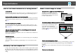
Projecting with "Connect to a Network Projector" "Connect to a Network Projector" is a standard function in Windows Vista and Windows 7. You can project images from the computer by detecting the projector on the network only by using a function of the OS without having to install any special software. 117 B On the computer, start Windows, and then click "Start" - "All programs" - "Accessories" - "Connect to a Network Projector". The connection setting screen is displayed.
Making a WPS (Wi-Fi Protected Setup) Connection with a Wireless LAN Access Point There are two methods for setting WPSg. • Push Button Method SSID and security are set automatically when the [Enter] button is pressed on the projector's control panel and the dedicated button on the access point equipment. This method is recommended when the projector and access point are close together.
Making a WPS (Wi-Fi Protected Setup) Connection with a Wireless LAN Access Point When connecting using the Push Button Method, follow the steps given below. Go to "Making a connection using the PIN Code Method" when connecting using the "PIN Code Method". s p.120 119 The Push Button Method screen is displayed. B Press the [Enter] button on the projector's control panel when prompted by the screen. Making a connection using the push button method Procedure A Select "Push Button Method".
Making a WPS (Wi-Fi Protected Setup) Connection with a Wireless LAN Access Point This completes the setup. D Press the [Enter] button or the [Esc] button. 120 This completes the setup of the connection between the projector and the access point. Press the [Menu] button to close the configuration menu. Making a connection using the PIN Code Method q Before you can make a connection using the "PIN Code Method", a connection must have already been setup between the computer and the access point.
Making a WPS (Wi-Fi Protected Setup) Connection with a Wireless LAN Access Point The PIN Code Method screen is displayed. B Enter the PIN code displayed on the "PIN Code Method" screen C The message "Setup by Wi-Fi Protected Setup complete." is displayed. Press the [Enter] button or the [Esc] button. from the computer to the access point, and then select "Start Setup". It returns to the Wireless LAN menu screen. The progress is displayed. 121 D Select "Setup complete" - "Yes.
Making a WPS (Wi-Fi Protected Setup) Connection with a Wireless LAN Access Point This completes the setup of the connection between the projector and the access point. Press the [Menu] button to close the configuration menu.
Installation and Connections This chapter explains the projection installation methods and methods to connect to other equipment.
Installation Methods The projector can be mounted on a ceiling or placed on a desk as shown below. Warning 124 • Suspend the projector from the ceiling and project images from in front of a screen. (Front/Ceiling projection) • Suspend the projector from the ceiling and project images from behind a translucent screen. (Rear/Ceiling projection) • Project images from in front of the screen. (Front projection) • Project images from behind a translucent screen.
Installation Methods Each time this button is pressed for at least 5 seconds, the Projection setting will switch between Front and Front/Ceiling. The orientation of the projected image will change accordingly. To set Rear or Rear/Ceiling, use the Projection setting on the Extended menu. s p.57 q When suspending the projector from a ceiling, set the Inv Direction Button on the Extended menu to On so that the [ ], [ ], [ ], and [ ] buttons on the control panel operate in the correct directions.
Connecting to Video Equipment 126 Observe the following precautions when connecting the projector to external equipment. Be sure to also read the documentation for the external equipment. Attention • Turn off the projector and the external equipment. The projector or external equipment may fail if they are connected while the power is on. • Check the shapes of the cable connector and port before connecting them.
Connecting to Video Equipment Computer port Connection 2 Connection 3 Connection 4 q 127 Connecting cable Monitor Out port Computer cable (supplied) Audio Out port Audio cable (commercially available) DVI-D output DVI-D cable (commercially available) Audio Out port Audio cable (commercially available) HDMI output HDMI cable (commercially available) • Use a cable that complies with the HDMI standard for the HDMI cable.
Connecting to Video Equipment 128 Changing the video output from a laptop computer. When projecting images from a laptop computer connected to the projector with a computer cable, the output for the video signal must sometimes be changed at the computer. Refer to the documentation for your computer for the method to change the video output.
Connecting to Video Equipment Port on the video equipment Connection 3 Connection 4 Connection 5 129 Connecting cable Audio Out port Audio cable (commercially available) S-Video output S-Video cable (commercially available) Audio Out port Audio cable (commercially available) Video output Video cable (commercially available) Audio Out port Audio cable (commercially available) Video output BNC video cable (commercially available) Projector port S-Video input port Audio4 input port Video2
Connecting to Video Equipment Port on the video equipment Connection 6 q 130 Connecting cable Audio Out port Audio cable (commercially available) HDMI output HDMI cable (commercially available) Projector port HDMI input port • Set the input signal and video signal on the Signal menu according to the signal from the connected equipment. s p.53 • Use a cable that complies with the HDMI standard for the HDMI cable.
Connecting to External Equipment Connecting a LAN Cable Connect with a commercially available 100BASE-TX or 10BASE-T LAN cable. Connected equipment LAN port on network hub Connecting cable LAN cable (commercially available) 131 q Only analog RGB signals from a computer connected to the Computer1 input port or the BNC input port can be displayed on an external monitor. Images from equipment connected to other ports and component video signals cannot be displayed.
Connecting to External Equipment q • When an audio cable plug is inserted in the Audio Out port, the audio changes to the external destination, and audio is no longer emitted from the projector's built-in speaker. • When using a commercially available 2RCA(L/R)/stereo mini-pin audio cable, make sure it is labeled "No resistance".
Installing Optional and Supplied Accessories 133 Removing and Attaching the Projector Lens Unit Removing Attention • Only remove the lens unit when necessary. If dust or dirt enter the projector, projection quality deteriorates and it could cause a malfunction. • Try not to touch the lens section with your hand or fingers. If fingerprints or oils are left on the surface of the lens, projection quality deteriorates.
Installing Optional and Supplied Accessories 134 Attaching Attention Do not attach the lens unit when the projector's lens insertion section is facing up. Dust or dirt could enter the projector. Procedure A Turn clockwise until the focus ring stops moving. C Check that the lens cannot be detached by turning it anticlockwise. B Insert the lens unit straight into the lens insertion section with the white circle on the lens on top, and then turn clockwise until you hear it click into place.
Installing Optional and Supplied Accessories 135 A Screw hole to fix Wireless LAN unit B Install the Wireless LAN unit. When connecting a projector to which the Wireless LAN unit is mounted to a computer using a wireless LAN, set the Wireless LAN Power setting on the Wireless LAN menu to On. (The default setting is On.) s p.63 Reading the wireless LAN indicators There are two Wireless LAN indicators, one on the projector and one on the Wireless LAN unit.
Installing Optional and Supplied Accessories : Flashing Status Indicator on projector : Lit 136 : Off Indicator on Wireless LAN unit The Wireless LAN unit not mounted or the Wireless LAN Power setting on the Wireless LAN menu is Off The Wireless LAN unit mounted to the projector but not connected to the network B Insert the tabs on the cable cover into the two holes on the back of the projector.
Installing Optional and Supplied Accessories Removing Procedure Loosen the two cable cover screws and then remove the cable cover.
Appendix
Optional Accessories and Consumables The following optional accessories and consumables are available. Please purchase these products as and when needed. The following list of optional accessories and consumables is current as of: 2010.10. Details of accessories are subject to change without notice and availability may vary depending on the country of purchase. Optional accessories Computer cable ELPKC02 (1.
Optional Accessories and Consumables Consumables Lamp unit (EB-G5750WU) ELPLP63 Lamp unit (EB-G5450WU) ELPLP62 Use as a replacement for used lamps. Air filter ELPAF17 Use as a replacement for used air filters.
Screen Size and Projection Distance 141 The following table shows the projection distance when a standard lens is attached. When an optional lens is attached, check the projection distances using the Lens Projection Distance Table supplied with this projector. To find the appropriate screen size, see the following table to set up the projector. Values are just reference.
Screen Size and Projection Distance 142 Units: cm 16:10 Screen size Minimum (Wide) to Maximum (Tele) Vertical lens shift Maximum to Minimum 50" 110x67 136 - 246 -6 - +73 60" 130x81 164 - 296 -7 - +88 80" 170x110 220 - 397 -9 - +117 100" 220x130 276 - 497 -11 - +146 120" 260x160 332 - 597 -13 - +175 150" 320x200 417 - 747 -17 - +219 200" 430x270 557 - 998 -22 - +292 250" 540x340 698 - 1248 -28 - +365 300" 640x400 838 - 1499 -34 - +438
Supported Monitor Displays 143 Component Video Supported Monitor Displays Computer signals (analog RGB) Signal Refresh Rate (Hz) Resolution (dots) SDTV(480i) 60 720x480 Signal Refresh Rate (Hz) Resolution (dots) SDTV(576i) 50 720x576 VGA 60/72/75/85 640x480 SDTV(480p) 60 720x480 SVGA 56/60/72/75/85 800x600 SDTV(576p) 50 720x576 XGA 60/70/75/85 1024x768 HDTV(720p) 50/60 1280x720 WXGA 60 1280x768 HDTV(1080i) 50/60 1920x1080 60 1360x768 60/75/85 1280x800 WXGA+ 60/75
Supported Monitor Displays * 144 Signal Refresh Rate (Hz) Resolution (dots) SDTV(480i) 60 720x480 SDTV(480p) 60 720x480 SDTV(576i) 50 720x576 SDTV(576p) 50 720x576 HDTV(720p) 50/60 1280x720 HDTV(1080i) 50/60 1920x1080 HDTV(1080p) 24/30/50/60 1920x1080 Only compatible when VESA CVT-RB (Reduced Blanking) signal is input.
Specifications 145 Projector General Specifications EB-G5750WU Product name EB-G5450WU 470 (W) ^ 135 (H) ^ 311.5 (D) mm (not including foot and projection lens) Dimensions 0.76" wide Panel size Polysilicon TFT active matrix Display method 2,304,000 pixels WUXGA (1920 (W) ^ 1200 (H) dots) ^ 3 Resolution Manual Focus adjustment Manual (1 to 1.8) Zoom adjustment *1 Manual (vertical: approx. 58% max., horizontal: approx. 9% max.) Lens shift *1 UHE lamp, 330 W Model No.
Specifications 146 EB-G5750WU Product name Connectors * EB-G5450WU Computer1 input port 1 Mini D-Sub15-pin (female) blue Audio1 input port 1 Stereo mini jack DVI-D input port 1 DVI-D 24pin Single Link HDCP compatible Audio2 input port 1 Stereo mini jack BNC input port 1 5BNC (female) Audio3 input port 1 Stereo mini jack Video1 input port 1 1BNC (female) Video2 input port 1 RCA pin jack S-Video input port 1 Mini DIN 4-pin Audio4 input port 1 RCA pin jack ^ 2 (L, R) HDMI in
Specifications Angle of tilt Using the projector at angles not shown in the illustrations above may damage it or cause an accident.
Specifications 148 DECLARATION of CONFORMITY According to 47CFR, Part 2 and 15 Class B Personal Computers and Peripherals; and/or CPU Boards and Power Supplies used with Class B Personal Computers We: Located at: Tel: Epson America, Inc. 3840 Kilroy Airport Way MS: 3-13 Long Beach, CA 90806 562-290-5254 Declare under sole responsibility that the product identified herein, complies with 47CFR Part 2 and 15 of the FCC rules as a Class B digital device.
Appearance 149 Units: mm A Center of lens B Distance from center of lens to suspension bracket fixing point
Glossary 150 This section explains easily terms that are used with the projector and difficult terms that are not explained in the text of this guide. For details, refer to other commercially available publications. Ad hoc mode A method of wireless LAN connection that communicates with wireless LAN clients without using an access point. It is not possible to communicate with two or more devices simultaneously.
Glossary 151 Interlace A method of image scanning whereby the image data is divided into fine horizontal lines that are displayed in sequence starting from left to right and then from top to bottom. The even-numbered lines and odd-numbered lines are displayed alternately. IP Address A number to identify a computer connected to a Network. Progressive A method of image scanning whereby the image data from a single image is scanned sequentially from top to bottom to create a single image.
General Notes All rights reserved. No part of this publication may be reproduced, stored in a retrieval system, or transmitted in any form or by any means, electronic, mechanical, photocopying, recording, or otherwise, without the prior written permission of Seiko Epson Corporation. No patent liability is assumed with respect to the use of the information contained herein. Neither is any liability assumed for damages resulting from the use of the information contained herein.
General Notes 153 Software Copyright: This product uses free software as well as software to which this company holds the rights. The following is information on the free software used by this product. ©SEIKO EPSON CORPORATION 2010. All rights reserved. 1. LGPL 2. (1) This company uses free software for this product under the terms of the GNU LESSER General Public License Version 2, June 1991 (henceforth "LGPL") or later versions. You can see the full text of the LGPL on the following Web sites.
General Notes As well as the free software used under the terms of the LGPL, this company also uses the following free software for this product. Hereafter, each author, the conditions, and so on are described in the original.
General Notes We protect your rights with two steps: (1) copyright the software, and (2) offer you this license which gives you legal permission to copy, distribute and/or modify the software. Also, for each author's protection and ours, we want to make certain that everyone understands that there is no warranty for this free software.
General Notes a) 4. 5.
General Notes 157 9. 12. 11. END OF TERMS AND CONDITIONS How to Apply These Terms to Your New Programs If you develop a new program, and you want it to be of the greatest possible use to the public, the best way to achieve this is to make it free software which everyone can redistribute and change under these terms. To do so, attach the following notices to the program.
General Notes Gnomovision version 69, Copyright (C) year name of author Gnomovision comes with ABSOLUTELY NO WARRANTY; for details type `show w'. This is free software, and you are welcome to redistribute it under certain conditions; type `show c' for details. The hypothetical commands `show w' and `show c' should show the appropriate parts of the General Public License.
General Notes For example, if you distribute copies of the library, whether gratis or for a fee, you must give the recipients all the rights that we gave you. You must make sure that they, too, receive or can get the source code. If you link other code with the library, you must provide complete object files to the recipients, so that they can relink them with the library after making changes to the library and recompiling it. And you must show them these terms so they know their rights.
General Notes 1. 2. Activities other than copying, distribution and modification are not covered by this License; they are outside its scope. The act of running a program using the Library is not restricted, and output from such a program is covered only if its contents constitute a work based on the Library (independent of the use of the Library in a tool for writing it). Whether that is true depends on what the Library does and what the program that uses the Library does.
General Notes 5. 6. 161 a) A program that contains no derivative of any portion of the Library, but is designed to work with the Library by being compiled or linked with it, is called a "work that uses the Library". Such a work, in isolation, is not a derivative work of the Library, and therefore falls outside the scope of this License.
General Notes a) Accompany the combined library with a copy of the same work based on the Library, uncombined with any other library facilities. This must be distributed under the terms of the Sections above. b) Give prominent notice with the combined library of the fact that part of it is a work based on the Library, and explaining where to find the accompanying uncombined form of the same work. 8.
General Notes 15. 16. NO WARRANTY BECAUSE THE LIBRARY IS LICENSED FREE OF CHARGE, THERE IS NO WARRANTY FOR THE LIBRARY, TO THE EXTENT PERMITTED BY APPLICABLE LAW. EXCEPT WHEN OTHERWISE STATED IN WRITING THE COPYRIGHT HOLDERS AND/OR OTHER PARTIES PROVIDE THE LIBRARY "AS IS" WITHOUT WARRANTY OF ANY KIND, EITHER EXPRESSED OR IMPLIED, INCLUDING, BUT NOT LIMITED TO, THE IMPLIED WARRANTIES OF MERCHANTABILITY AND FITNESS FOR A PARTICULAR PURPOSE.
General Notes 1. Redistributions of source code must retain the above copyright notice, this list of conditions and the following disclaimer. 2. Redistributions in binary form must reproduce the above copyright notice, this list of conditions and the following disclaimer in the documentation and/or other materials provided with the distribution. 3.
General Notes 165 We specifically permit and encourage the use of this software as the basis of commercial products, provided that all warranty or liability claims are assumed by the product vendor. ansi2knr.c is included in this distribution by permission of L. Peter Deutsch, sole proprietor of its copyright holder, Aladdin Enterprises of Menlo Park, CA. ansi2knr.
General Notes Tom Lane Glenn Randers-Pehrson Willem van Schaik libpng versions 0.89, June 1996, through 0.96, May 1997, are Copyright (c) 1996, 1997 Andreas Dilger Distributed according to the same disclaimer and license as libpng-0.88, with the following individuals added to the list of Contributing Authors: John Bowler Kevin BraceySam Bushell Sam Bushell Magnus Holmgren Greg Roelofs Tom Tanner libpng versions 0.5, May 1995, through 0.
General Notes 1. The origin of this software must not be misrepresented; you must not claim that you wrote the original software. If you use this software in a product, an acknowledgment in the product documentation would be appreciated but is not required. 2. Altered source versions must be plainly marked as such, and must not be misrepresented as being the original software. 3. This notice may not be removed or altered from any source distribution. Jean-loup Gailly Mark Adler jloup@gzip.
General Notes License terms of conditions of each program which are provided by owner of the copyright to the “ncurses” are as follows. Copyright (c) 1998-2002,2003 Free Software Foundation, Inc.
Index 169 t indicator .................................................... 80 Color Adjustment ........................................ 52 Color Mode ............................................ 29, 51 Color Saturation .......................................... 51 Computer1 input port ................................. 12 Configuration Menu ................................... 50 Connect to a Network Projector ............. 117 Consumables .............................................. 140 Contrast .......
Index 170 Inv Direction Button ................................... 58 IP Address ..................................................... 71 K O Keystone ................................................. 23, 55 M MAC Address ............................................... 71 Mail menu ..................................................... 72 Mail Notification ................................. 72, 107 Message Broadcasting ............................... 104 Messages .........................................
Index Soft kyeboard ................................................ 61 Source ............................................................ 75 Source Left .................................................... 31 Source Right ................................................. 31 Source Search ................................... 13, 15, 25 Specifications ............................................. 145 Split Screen ............................................. 30, 55 Split Screen Setup .......................