ELPMB27 Short Throw Projector Wall Mount Installation Manual xxx(FR) xxx(DE) xxx(IT) xxx(ES) xxx(PT) xxx(ZHS)
Safety Instructions Before using the wall mount, make sure you read all of the safety instructions below and then save this manual for later reference. Incomplete or incorrect installation could cause damage to the product or result in personal injury or property damage. For additional information, see the User’s Guide and Safety Instructions included with your projector.
English Warning In order to resist vibration and support the weight of the projector and optional accessories, use M8 nuts and bolts and tighten all screws firmly after installation. Otherwise, the projector or wall mount may fall and cause personal injury or property damage. Epson accepts no responsibility for any damage or injury caused by lack of wall strength or inadequate installation. If you need to loosen any screws while installing, be careful not to drop the projector or the mount.
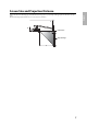
Before Use This product is used for mounting the following short throw projectors to a wall: EB-435W/EB-430/EB-425W/EB-420/ PowerLite 435W/PowerLite 430/PowerLite 425W/PowerLite 420. Choosing a Location Determine where you will install the wall mount and prepare the location in advance. Also, make sure there is a gap of 410 to 660 mm (16 to 26 inches) from the top of the image projected onto the white board to the ceiling. See "Screen Size and Projection Distance" on page 7 for more details.
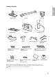
English Package Contents Adjustment unit Attachment plate Cable cover M4 x 12 mm hexagon socket head cap bolts with washers (x3) M8 x 12 mm hexagon socket head cap bolts without washers (x4) Arm unit Arm plate Wall plate Arm cover Wall plate cover Interface cover bracket M4 x 12 mm hexagon socket head cap bolts without washers (x6) M8 x 15 mm hexagon socket head cap bolts without washers (x3) Hexagonal wrenches (M4 and M8) M4 x 12 mm hexagon socket head cap bolts with washers/spring washers
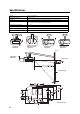
Specifications Weight Approx. 10 kg (22 lbs.) Maximum load capacity 5.5 kg (12.13 lbs.) Arm length 1510 mm (15.45 inches) (from wall plate attachment point to arm cover point) Vertical slide adjustment range 0 to 134 mm (0 to 5.27 inches) (arm length minimum) 0 to 230 mm (0 to 9.05 inches) (arm length maximum) Vertical tilt adjustment range 0 to - 9.
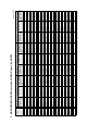
Screen Size and Projection Distance English Refer to the tables on the following pages and install the mount and projector to project images at the appropriate size. The values are only a guide. The recommended projection distance is 70 to 119 cm (27.55 to 46.85 inches).
70 (27.56) 71 (27.95) 72 (28.35) 73 (28.74) 74 (29.13) 75 (29.53) 77 (30.31) 78 (30.71) 79 (31.10) 80 (31.50) 81 (31.89) 82 (32.28) 83 (32.68) 84 (33.07) 85 (33.46) 86 (33.86) 87 (34.25) 88 (34.65) 90 (35.43) 91 (35.83) 92 (36.22) 93 (36.61) 94 (37.01) 95 (37.40) 96 (37.80) 97 (38.19) 60" 61" 62" 63" 64" 65" 66" 67" 68" 69" 70" 71" 72" 73" 74" 75" 76" 77" 78" 79" 80" 81" 82" 83" 84" 85" 86" 87" 88" 89" 90" 91" 92" 93" 4 (1.57) 5 (1.97) 5 (1.97) 5 (1.97) 5 (1.97) 5 (1.97) 5 (1.97) 5 (1.97) 5 (1.
Projection distance (A) Minimum (Tele) 70 (27.56) 119 (46.85) 69 (27.17) 119 (46.85) 69 (27.17) 119 (46.85) 6 (2.36) 6 (2.36) 6 (2.36) 7 (2.76) 7 (2.76) 7 (2.76) 7 (2.76) 7 (2.76) 7 (2.76) 7 (2.76) 7 (2.76) 7 (2.76) 7 (2.76) 7 (2.76) 7 (2.76) 7 (2.76) 7 (2.76) 7 (2.76) 7 (2.76) 7 (2.76) 16:10 WXGA Vertical slide adjustment (B) 0 17 (6.69) 0 17 (6.69) 5 (1.97) 23 (9.06) Vertical slide adjustment (B) Distance from top of projected image to ceiling (C) 48 (18.90) 48 (18.90) 48 (18.90) 49 (19.
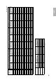
70 (27.56) 72 (28.35) 73 (28.74) 74 (29.13) 75 (29.53) 76 (29.92) 78 (30.71) 79 (31.10) 80 (31.50) 81 (31.89) 83 (32.68) 84 (33.07) 85 (33.46) 86 (33.86) 87 (34.25) 89 (35.04) 90 (35.43) 91 (35.83) 92 (36.22) 94 (37.01) 95 (37.40) 96 (37.80) 97 (38.19) 98 (38.58) 100 (39.37) 101 (39.76) 102 (40.16) 103 (40.55) 105 (41.34) 106 (41.73) 107 (42.13) 58" 59" 60" 61" 62" 63" 64" 65" 66" 67" 68" 69" 70" 71" 72" 73" 74" 75" 76" 77" 78" 79" 80" 81" 82" 83" 84" 85" 86" 87" 88" 89" 90" 11 (4.33) 12 (4.72) 12 (4.
Projection distance (A) Minimum (Tele) 70 (27.56) 119 (46.85) 69 (27.17) 118 (46.46) 70 (27.56) 119 (46.85) 16 (6.30) 16 (6.30) 16 (6.30) 17 (6.69) 17 (6.69) 17 (6.69) 17 (6.69) 17 (6.69) 17 (6.69) 17 (6.69) - 16:10 WXGA Vertical slide adjustment (B) 0 18 (7.09) 5 (1.97) 22 (8.66) 5 (1.97) 23 (9.06) Vertical slide adjustment (B) Distance from top of projected image to ceiling (C) 58 (22.83) 58 (22.83) 59 (23.23) 59 (23.23) 59 (23.23) 59 (23.23) 60 (23.62) 60 (23.62) 60 (23.62) 60 (23.62) 2 (0.
Assembly and Installation Make sure you follow the instructions below to install the wall mount. Otherwise, the wall mount may fall and result in personal injury or property damage. Warning ❏ When you mount the projector on the wall with the wall mount, the wall requires enough strength to hold the projector, optional accessories, and the wall mount. This wall mount should be installed on a concrete wall.
Position the wall plate over the marks you made in step 1, and then mark the points where the wall plate will be secured as shown in the following illustration. Insert the anchors into at least three points. If you insert four anchors, use the four point As or four point Bs as shown below. For 3 points 3) For 4 points Drill holes of the following diameters and depths at the points you marked. Drill diameter 8.5 mm (0.33 inches) Pilot hole depth 40 mm (1.57 inches) Anchor hole depth 35 mm (1.
2. Assembling the wall mount 1) 2) Attach the adjustment unit to the arm unit. Secure temporarily using the hexagonal wrenches (M4 and M8) and M4 x 12 mm hexagon socket head cap bolt and M8 x 15 mm hexagon socket head cap bolt. Arm unit M4 x 12 mm hexagon socket head cap bolt M8 x 15 mm hexagon socket head cap bolt Adjustment unit 3) Attach the arm plate using a hexagonal wrench (M8) and four M8 x 12 mm hexagon socket head cap bolts.
If you are installing ELPIU03 (sold separately), you also need to route the USB cable supplied with ELPIU03 through the arm unit. Arm unit USB cable for ELPIU03 Caution Problems may occur if you use this product without routing the cables through the arm unit. q Route the USB cable that connects ELPIU03 to the computer so that the type B connector emerges on the adjustment unit side. 4. Attaching the wall mount to the wall plate 1) 2) Attach the hook on the arm plate to the bar on the wall plate.
5. Attaching the attachment plate to the projector 1) 2) Place the projector upside down. Attach the attachment plate to the projector using the hexagonal wrench (M4) and five M4 x 12 mm bolts with washers/ spring washers.
1) 2) Loosen the screw on the arm.( ) Adjust the length of the arm using the measure on the bottom to match the projection distance recommended in "Screen Size and Projection Distance" on page 7.( 3) ) After adjusting the length, secure the arm position temporarily by tightening the screw on top.( ) 8. Connecting the cables Connect the power cord and other cables to the projector. If you are installing ELPIU03, see the Quick Setup Guide included with the product.
10. Turning on the projector and checking the screen 1) 2) 3) 4) Plug in the projector. Turn on the projector. Loosen the screws on the adjustment unit (A, B, C, and D) as shown below to adjust the screen position. Adjust the vertical slide (arm angle) using screw (E) on the bottom of the arm plate. The arm rises when you tighten the screw, and lowers when you loosen it. A: Vertical tilt adjustment: 0 to -9.
11. Attaching the interface cover bracket English Attach the interface cover bracket using the hexagonal wrench (M4) and two M4 x 12 mm bolts with washers. M4 x 12 mm hexagon socket head cap bolts (x2) with washers Interface cover bracket 12. Attaching the cable cover Take up the cable slack, and then secure the cable cover with the screws as shown below.
13. Attaching the wall plate cover Secure the wall plate cover with a hexagonal wrench (M4) and three M4 x 12 mm hexagon socket head cap bolts. Wall plate cover M4 x 12 mm hexagon socket head cap bolts (x3) Wall plate cover Installation, removal, and servicing of the projector should only be performed by a qualified technician. See the User’s Guide included with your projector for information about maintenance and repairs. Warning 20 ❏ Never loosen the bolts and nuts after installation.